Dev-Kit Manufacturing Guide
PCB Fabrication and Assembly
Build the vehicle PCBs using the standalone PCB assembly guides. These guides are the canonical source for ordering notes, interactive BOMs, stencil/reflow guidance, inspection images, and PCB-specific manual assembly steps.
This Dev-Kit Manufacturing Guide covers how the completed PCBs are installed into the vehicle during general assembly.
Harness Fabrication
Build harnesses using the standalone Harness Manufacturing Guide. It is the canonical source for nailboard diagrams, BOMs, wire prep, termination, and pinout maps.
This Dev-Kit Manufacturing Guide keeps only vehicle-side routing and installation notes, placed in the assembly steps where each harness is installed.
BOM for the Assembly
The complete, versioned bill of materials lives on the
Bill of Materials page, generated from the BOM master data
in bom/.
It covers structure parts, fasteners, equipment, harnesses, consumables,
and tools, with supplier links and a downloadable procurement CSV.
Preparation
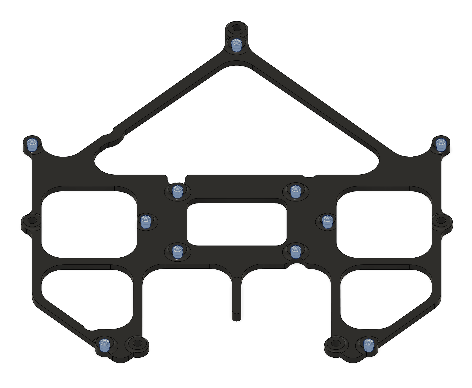
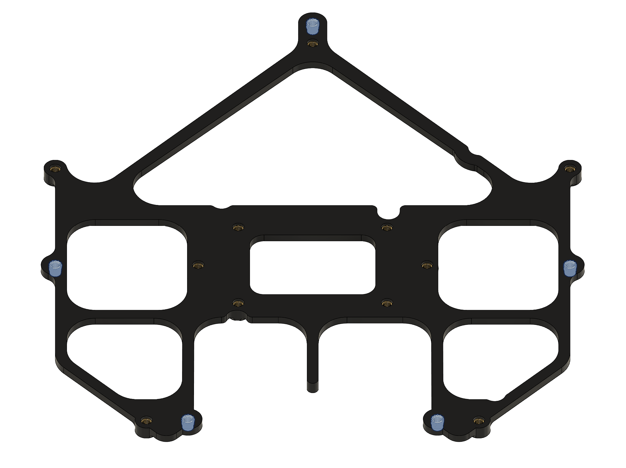
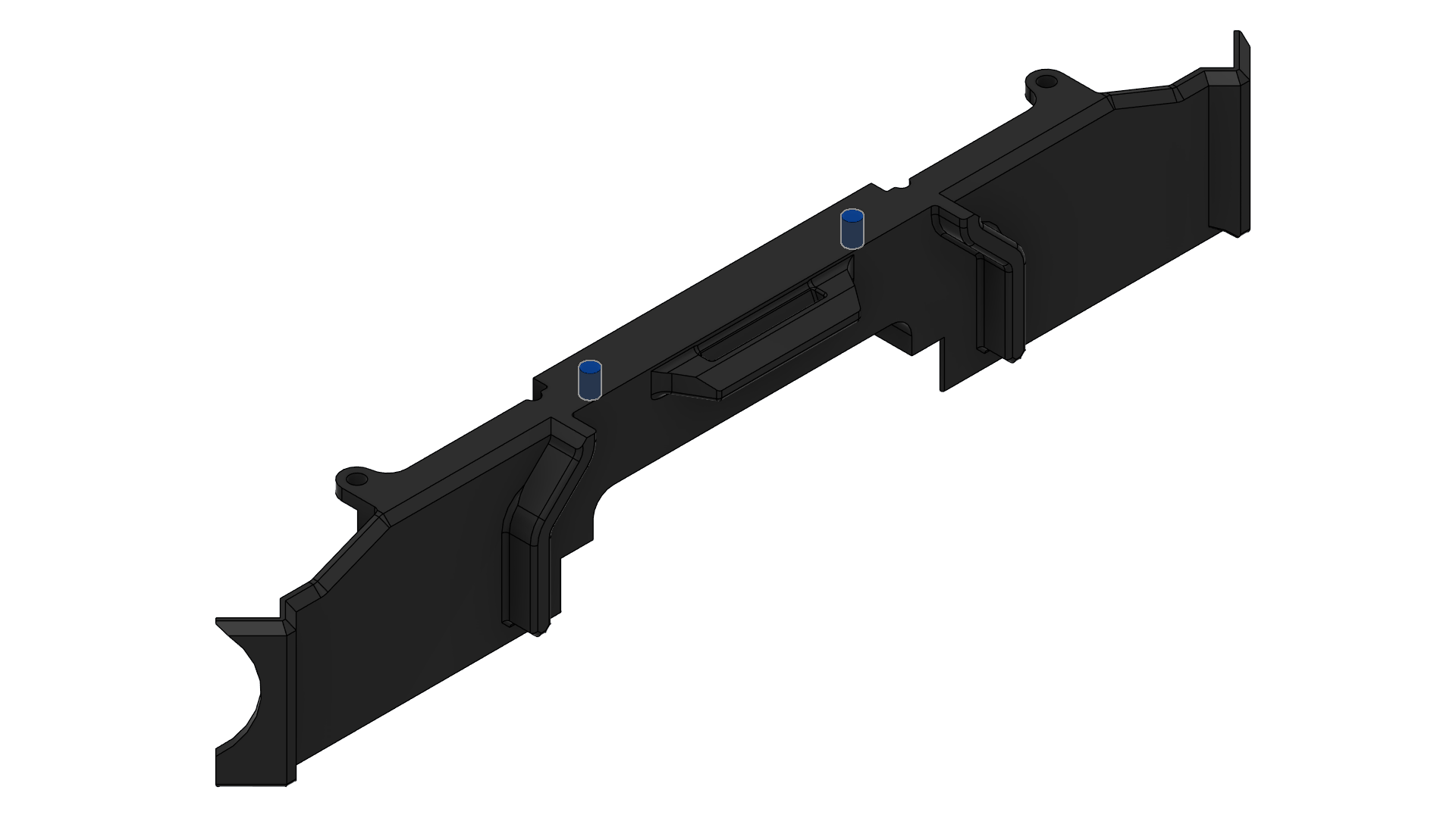
1111, 1112 & 1113 - Rack Plates
- All three are aluminum 6 series sheets, laser cut, sanded.
- Bounding box dimension is 300x300 mm for each.
- Qty: 1 each.
- Reference supplier: Rapiddirect
| 1111 (Upper Plate) | 1112 (Mid Plate) | 1113 (Lower Plate) |
|---|
| Thickness | 1 mm | 1 mm | 4 mm |
| Image | 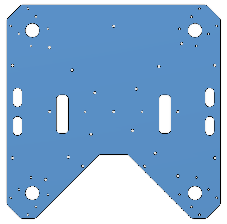 | 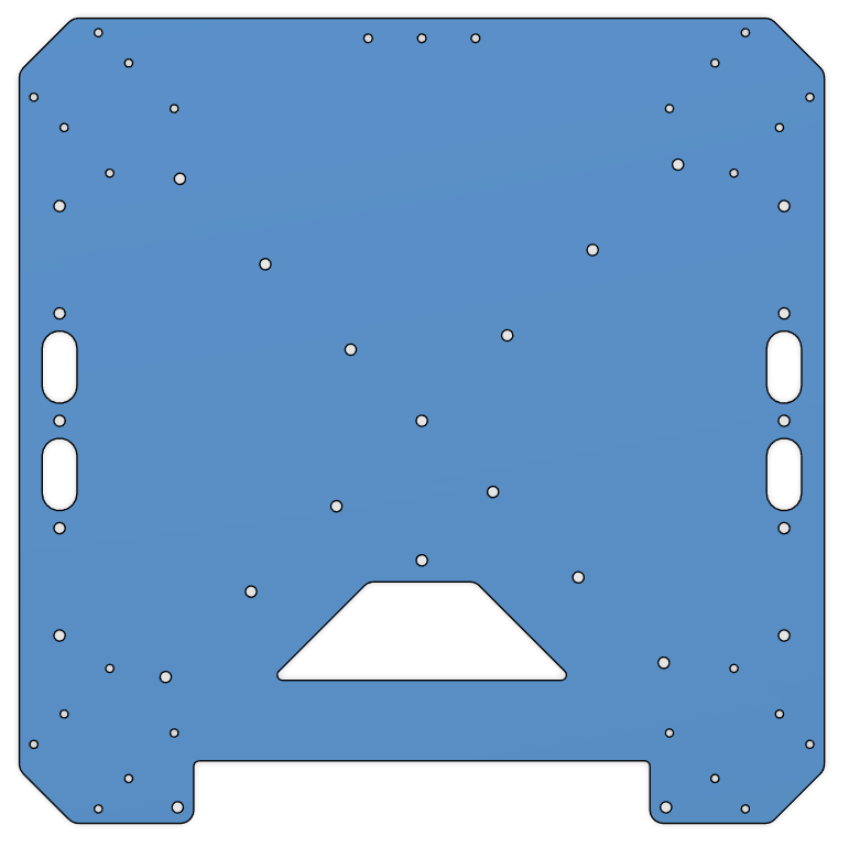 | 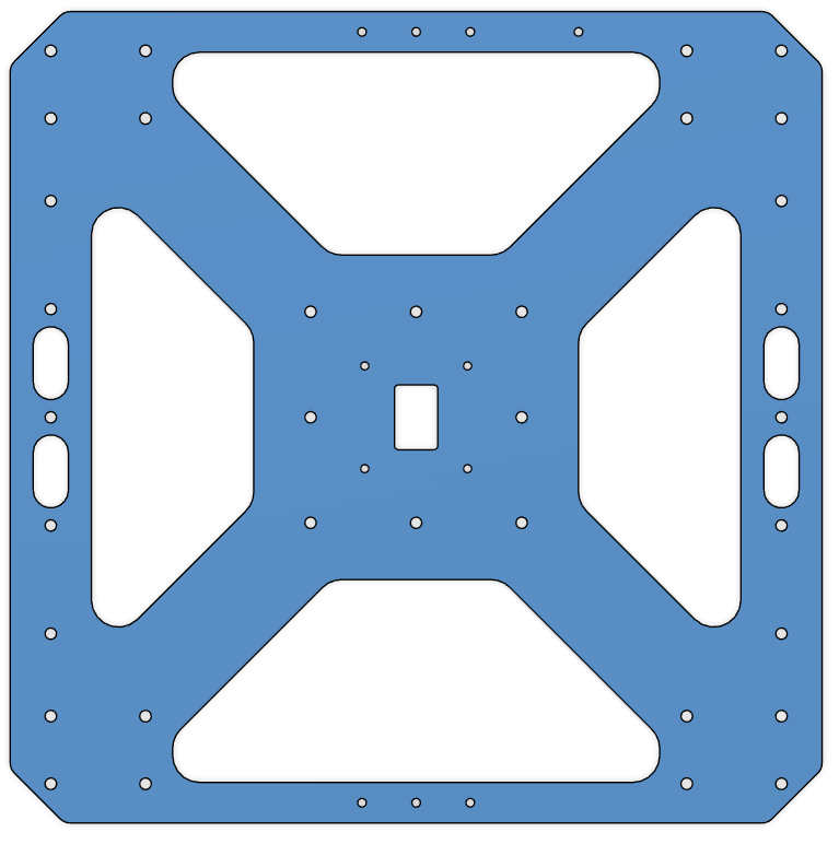 |
| CAD File | 1111 | 1112 | 1113 |
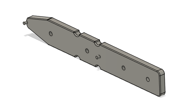
1211, 1212 & 1213 - Cockpit Support Beams
- All three are aluminum 6 series, 40x40x1 mm square tubes, laser cut, sanded.
- Part 1211; Qty: 1.
- Parts 1212 and 1213 are identical; Qty: 2.
- Reference supplier: Rapiddirect
| 1211 (Cockpit Support Beam CW Long) | 1212 & 1213 (Cockpit Support Beam CCW Back & Front) |
|---|
| Length | 289.2 mm | 124.2 mm |
| Image | 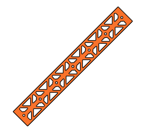 | 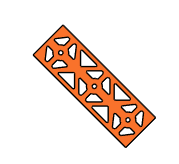 |
| CAD File | 1211 | 1212 & 1213 |
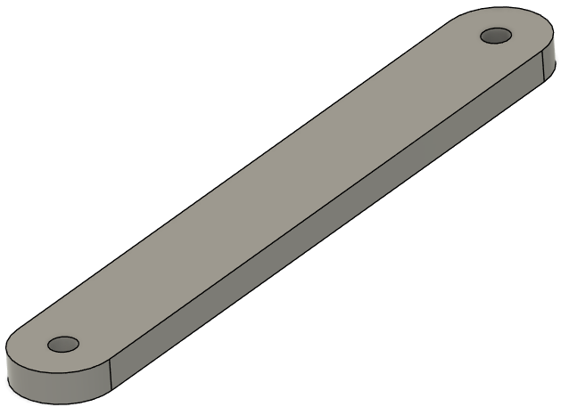
1221 & 1222 - Battery Walls
- Both are aluminum 6 series, 1000x30x2 mm rectangular tubes, laser cut, sanded.
- Length is 300 mm for each.
- Parts are identical; Qty: 2.
- Reference supplier: Rapiddirect
| 1221 & 1222 (Battery Wall Left & Right) |
|---|
| Image | 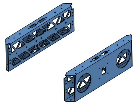 |
| CAD File | 1221 & 1222 |
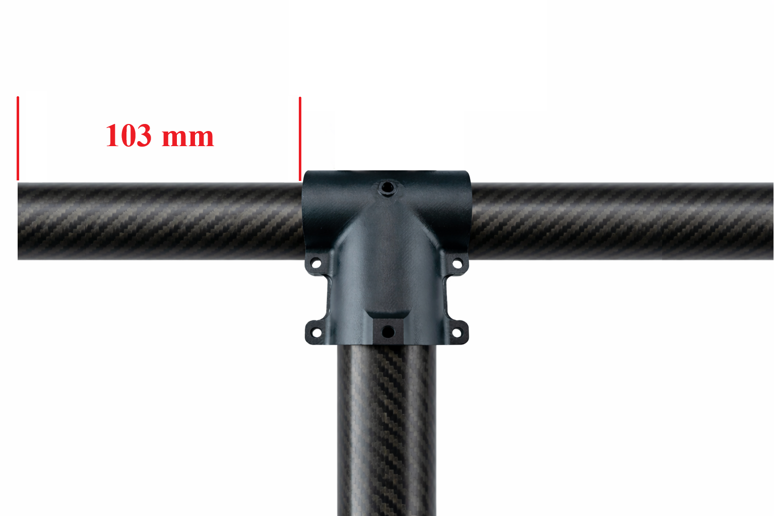
1311, 1312, 1313 & 1314 - Landing Gear Vertical Tubes
- Carbon-fiber tubes, 30 mm diameter, 1 mm thickness.
- Length is 400 mm for each.
- Parts are identical; Qty: 4.
- Note: Order parts pre-cut to the specified length if available; otherwise, cut to length.
1321 & 1322 - Landing Gear Horizontal Tubes
- Carbon-fiber tubes, 30 mm diameter, 1 mm thickness.
- Length is 500 mm for each.
- Parts are identical; Qty: 2.
- Note: Order parts pre-cut to the specified length if available; otherwise, cut to length.
1331, 1332, 1333 & 1334 - Landing Gear Main Adapters
- Off-the-shelf component.
- 30 mm option.
- Product Link: Link
- Qty: 4.
- This product became available in RJXHobby catalog after a customized order for 30 mm tube diameter.
- If not available in the catalog, contact RJXHobby for the customization.
- Request 30 mm diameter variant of this product with bolt pattern of 30 mm version of this one.
If detachable landing gear is not favored, you may use 30 mm version of this product.
| 1331, 1332, 1333 & 1334 (Landing Gear Main Adapter) |
|---|
 |
1341, 1342, 1343 & 1344 - Landing Gear Tube Joints
- Off-the-shelf component.
- Product Link: Link
- Qty: 4.
| 1341, 1342, 1343 & 1344 (Landing Gear Tube Joint) |
|---|
| Image | 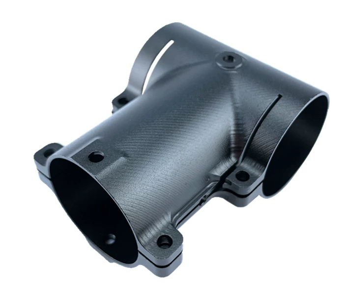 |
1351, 1352, 1353 & 1354 - Landing Gear Foam Wraps.
- Pipe insulation foam, 28 mm inner diameter, 46 mm outer diameter.
- Length is 103 mm each.
- Parts are identical; Qty: 4.
- Cut from stock material to length.
- Product Link: Link
| 1351, 1352, 1353 & 1354 (Landing Gear Foam Wrap) |
|---|
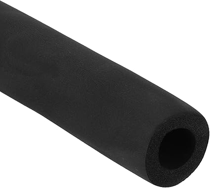 |
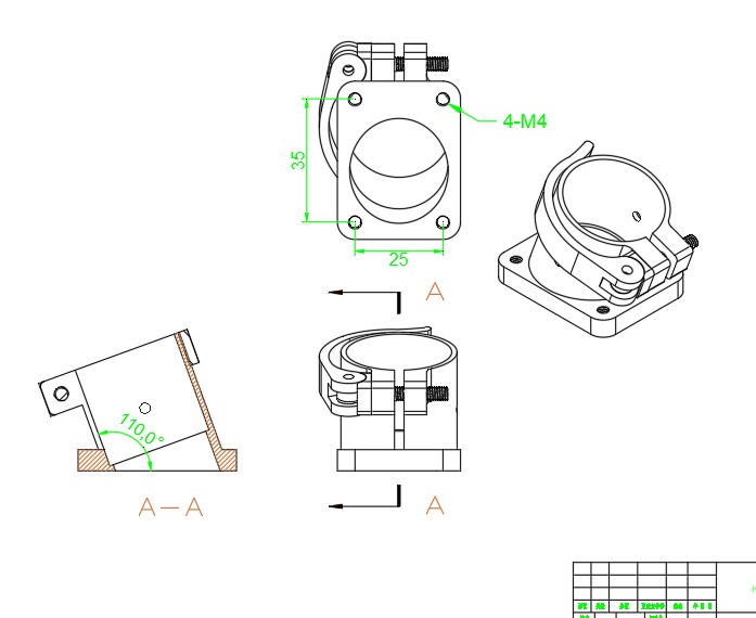
1411, 1421, 1431 & 1441 - Motor Arm Foldable Connectors
- 30 mm tube diameter version.
- Parts are identical; Qty: 4.
- Product Link: Link
| 1411, 1421, 1431 & 1441 (Motor Arm Foldable Connectors) |
|---|
 |
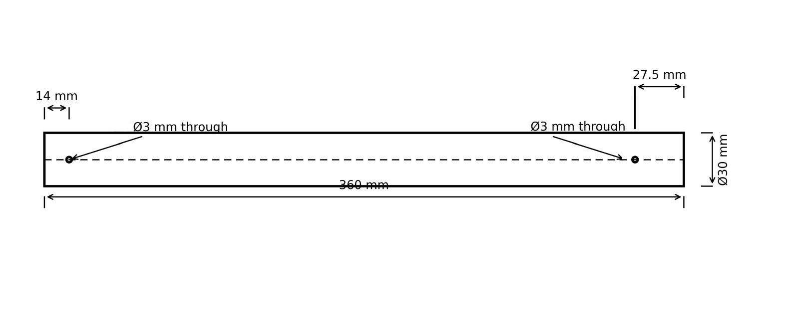
1412, 1422, 1432 & 1442 - Motor Arms
- Carbon-fiber tubes, 30 mm diameter, 1 mm thickness.
- Length is 360 mm for each.
- Parts are identical; Qty: 4.
- Note: Order parts pre-cut to the specified length if available; otherwise, cut to length.
2111, 2121 & 2131 - Attachment Interface Spacers
- 3D printed.
- PETG-CF.
- Use 6 wall loops.
- Parts 2111 and 2121 are identical; Qty: 2.
- Part 2131; Qty: 1.
| 2111 & 2121 (Attachment Interface Spacers, Left and Right) | 2131 (Attachment Interface Spacer, Bottom) |
|---|
| Image | 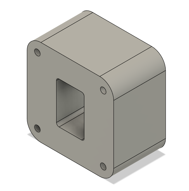 | 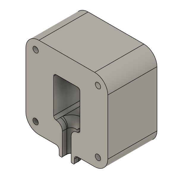 |
| CAD File | 2111 & 2121 | 2131 |
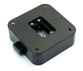
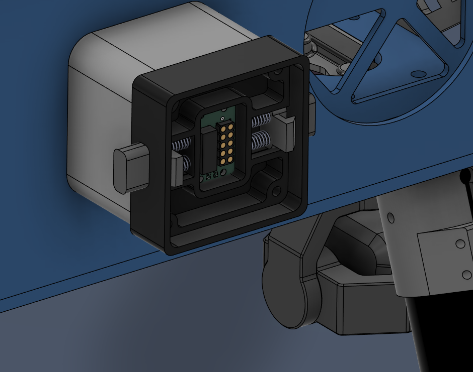
2112, 2122 & 2132 - Attachment Interfaces
- Parts are identical, order 3 parts.
- Select "Without PCB Board" option.
- Product Link: Link
| 2112, 2122 & 2132 (Attachment Interface) |
|---|
 |
2211 & 2212 - Battery Sliders
- 3D printed.
- PETG-CF.
- Use 6 wall loops.
- Parts are identical; Qty: 2.
2311 - Main PCB Mount
- 3D printed.
- PETG-CF.
- Use 6 wall loops.
- Qty: 1.
| 2311 (Main PCB Mount) |
|---|
| Image |  |
| CAD File | 2311 |
2312 - Battery Connector PCB Mount
- 3D printed.
- PETG-CF.
- Use 6 wall loops.
- Qty: 1.
| 2312 (BC PCB Mount) |
|---|
| Image | 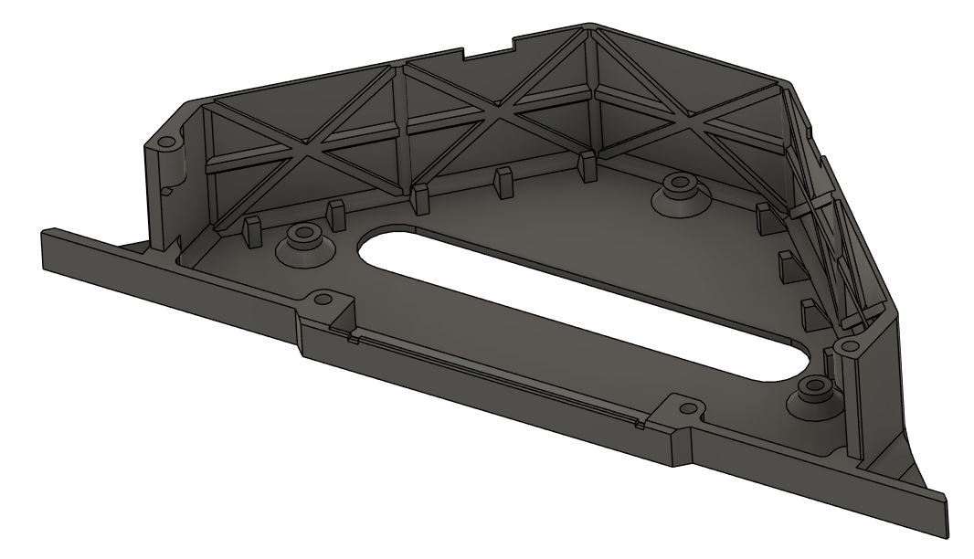 |
| CAD File | 2312 |
2313 - Battery Connector PCB Cover
- 3D printed.
- PETG-CF.
- Use 6 wall loops.
- Qty: 1.
| 2313 (BC PCB Cover) |
|---|
| Image | 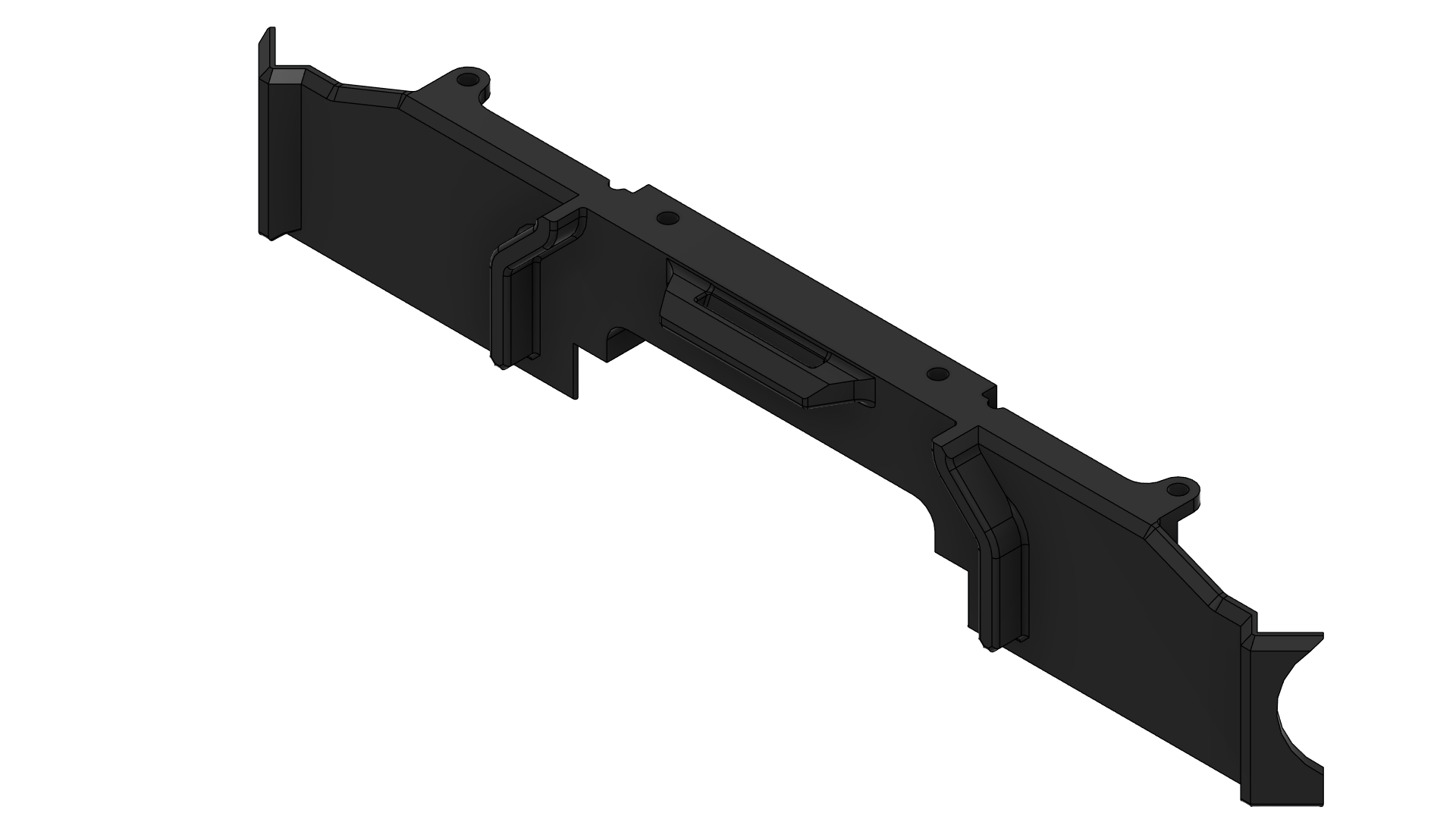 |
| CAD File | 2313 |
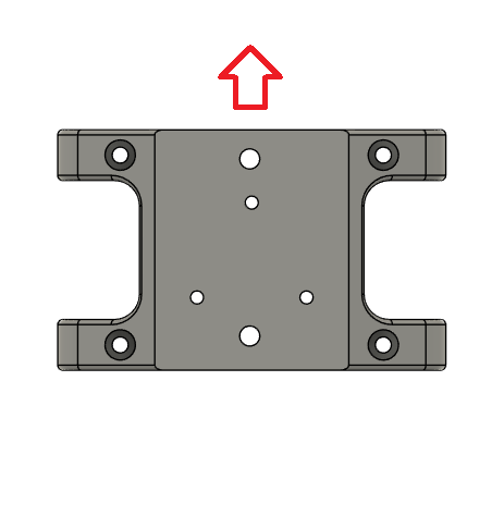
2321 - Sensor Mount
- 3D printed.
- PETG-CF.
- Use 6 wall loops.
- Qty: 1.
| 2321 (Sensor Mount) |
|---|
| Image | 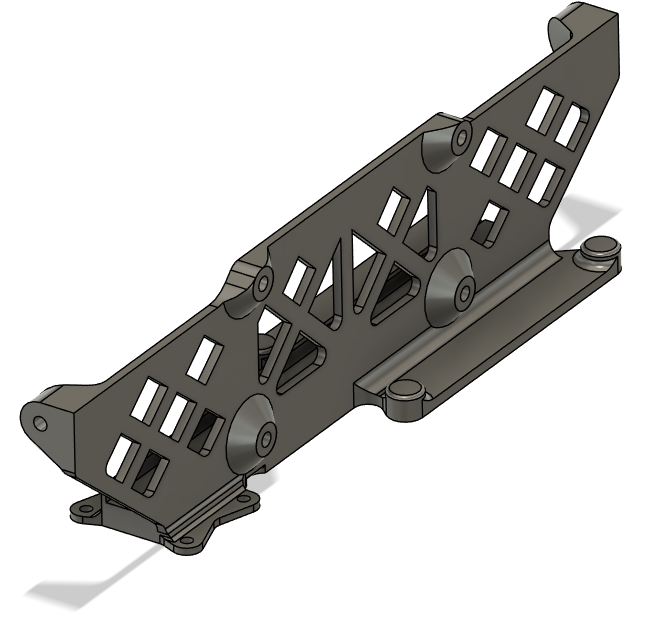 |
| CAD File | 2321 |
2331 - GNSS Mount
- 3D printed.
- PETG-CF.
- Use 6 wall loops.
- Qty: 1.
| 2331 (GNSS Mount) |
|---|
| Image | 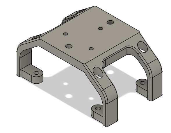 |
| CAD File | 2331 |
2341 - PPP & Beacon Mount
- 3D printed.
- PETG-CF.
- Use 6 wall loops.
- Qty: 1.
| 2341 (PPP & Beacon Mount) |
|---|
| Image | 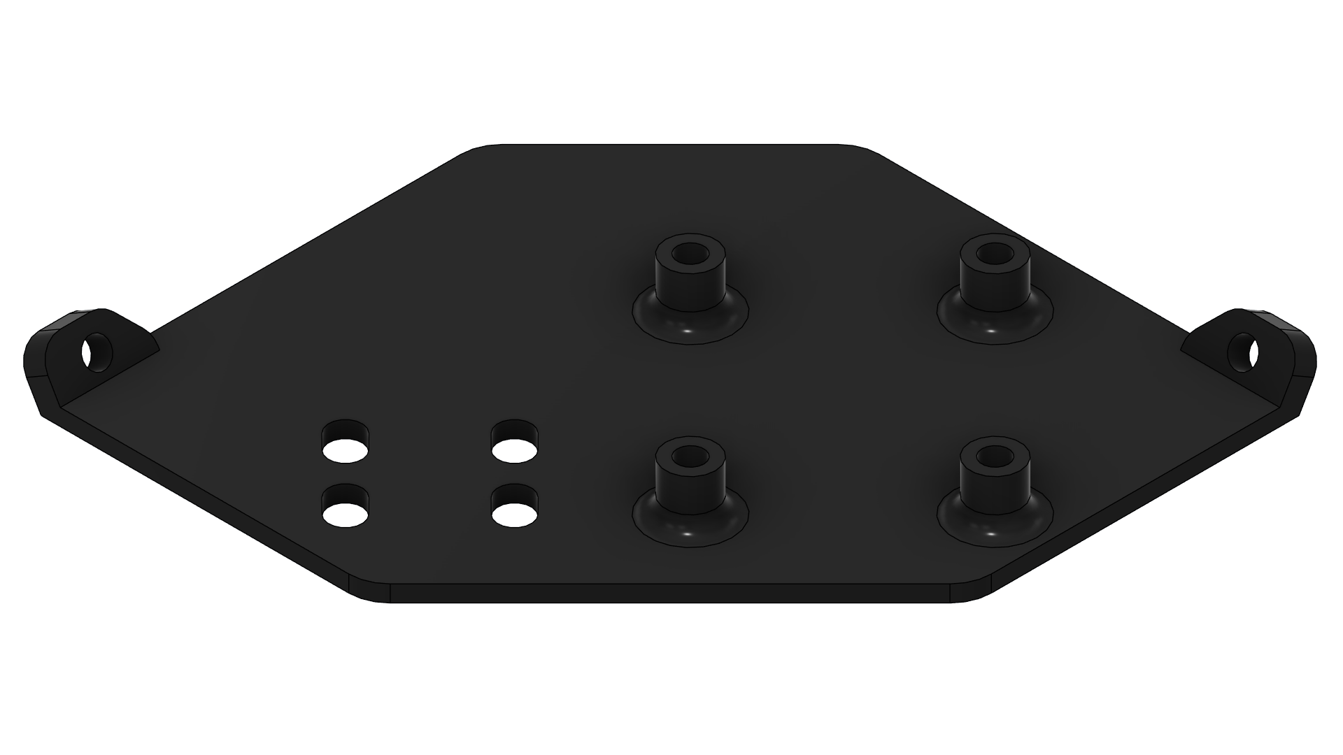 |
| CAD File | 2341 |
2411 - Main Enclosure
- 3D printed.
- PETG-CF.
- Use 6 wall loops.
- Qty: 1.
| 2411 (Main Enclosure) |
|---|
| Image | 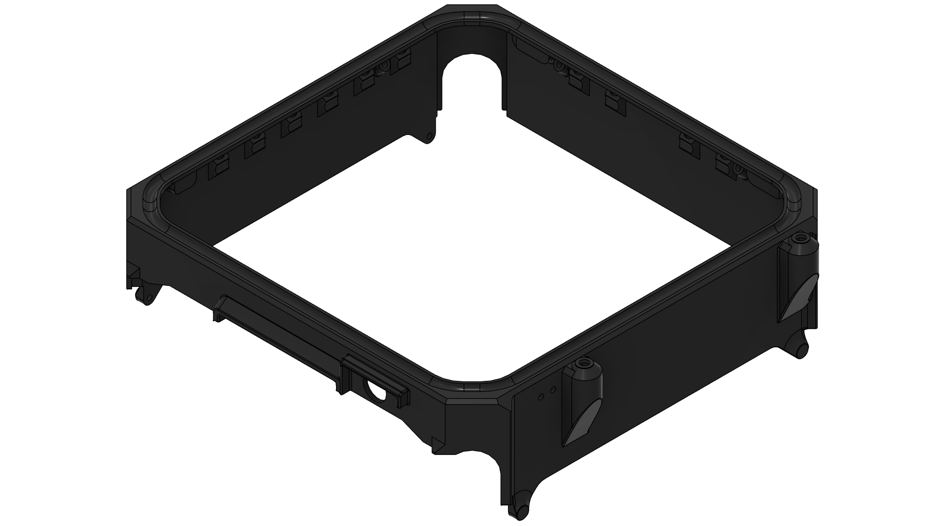 |
| CAD File | 2411 |
2412 - Top Cap
- 3D printed.
- PETG-CF.
- Use 6 wall loops.
- Mind the print orientation as shown.
- Qty: 1.
| 2412 (Top Cap) |
|---|
| Image | 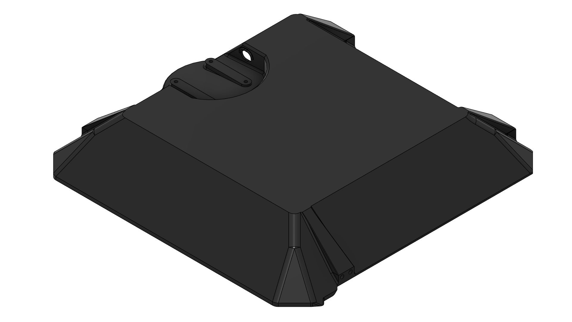 |
| Print Orientation | 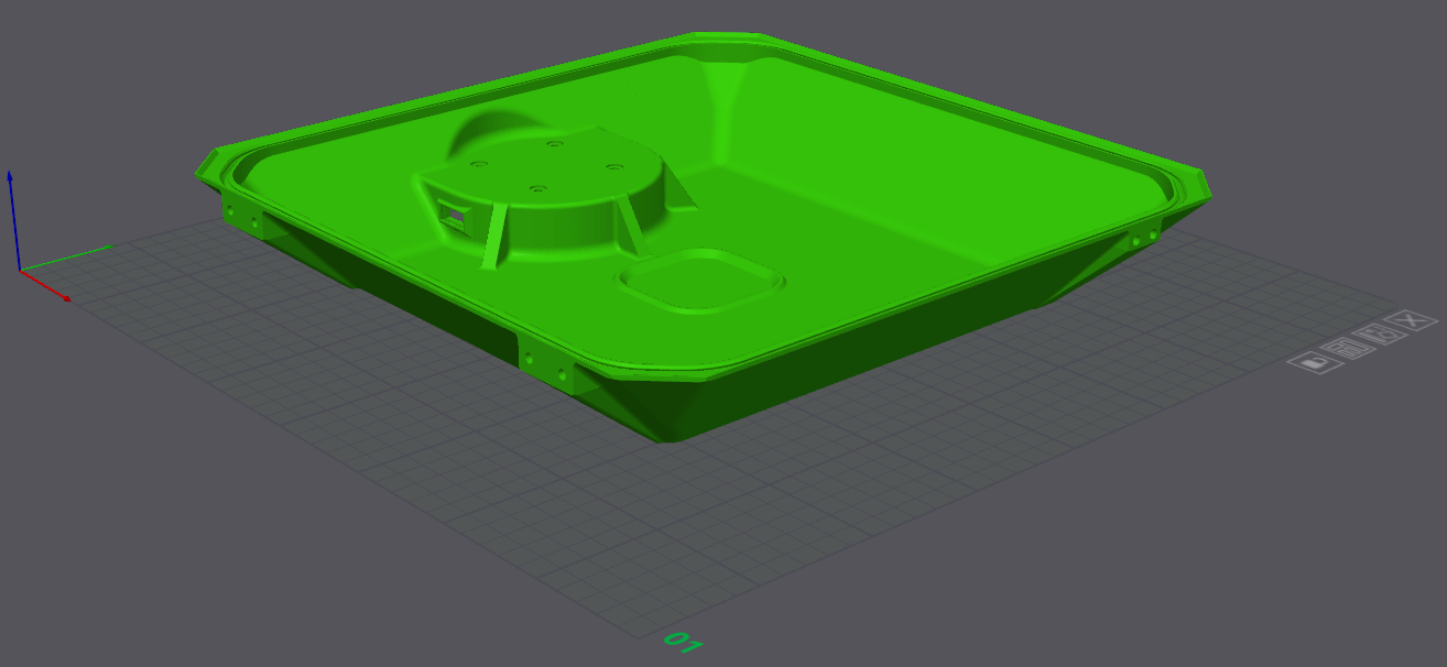 |
| CAD File | 2412 |
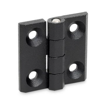
2421 & 2422 - Enclosure Hinges
- Off-the-shelf component.
- Part Number: GN 237-ZD-30-30-A-SW
- Product Link: Link
- Qty: 2.
| 2421 & 2422 (Enclosure Hinges) |
|---|
 |
2431 & 2432 - Enclosure Latches
- Off-the-shelf component.
- Screw on draw latch.
- Parts are identical; Qty: 2.
- Product Link:
- US: Link
- UK: Latch and catch plate are sold separately.
3322 & 3323 - Busbars
- Both are Copper C110 | CU ETP, laser cut, bent.
- Bounding box dimension is 300x300 mm for each.
- Qty: 1 each.
- Reference supplier: Rapiddirect
| 3322 (Busbar Positive) | 3323 (Busbar Negative) |
|---|
| Image | 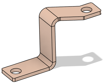 | 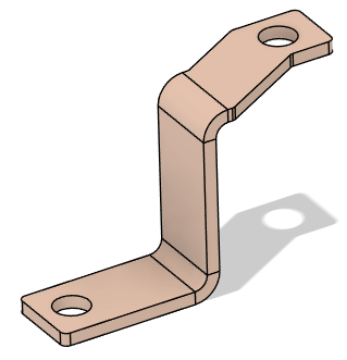 |
| CAD File | 3322 | 3323 |
| -- | | |
3324 - BC PCB Heatsink
- Aluminum 6 series, laser cut, sanded.
- Experimental part:
- Order both 4 mm and 5 mm thickness variants for evaluation.
- Qty: 1 each.
- Reference supplier: Rapiddirect
Assembly Steps
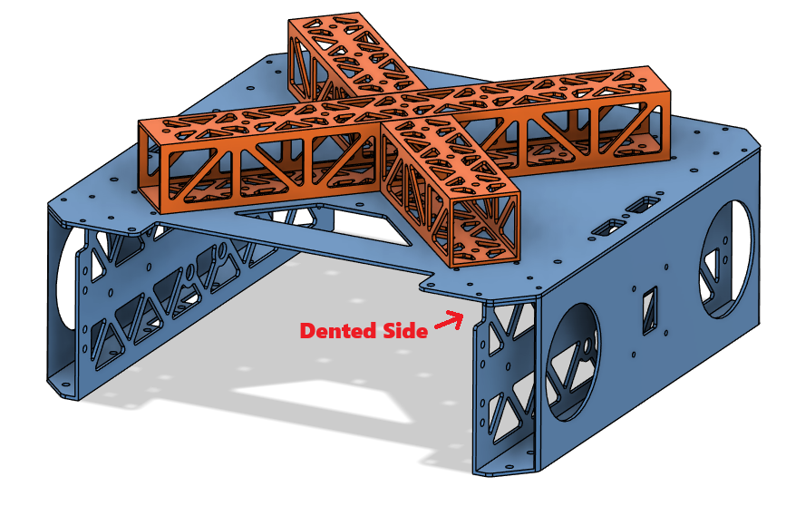
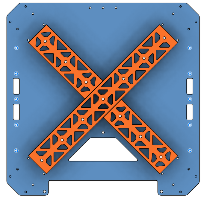
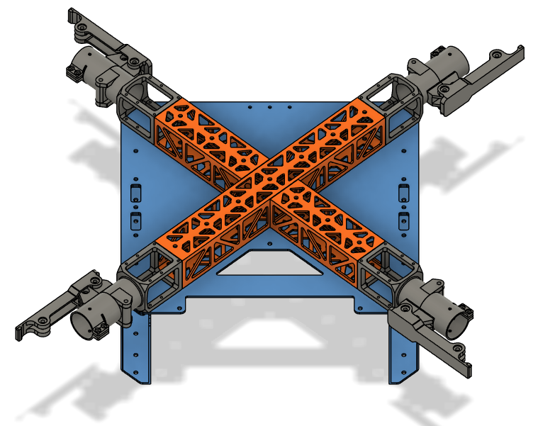
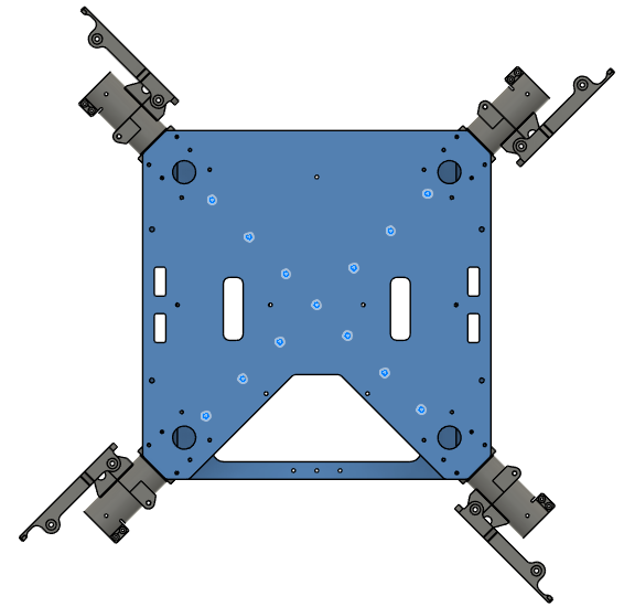
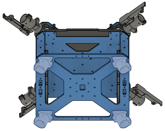
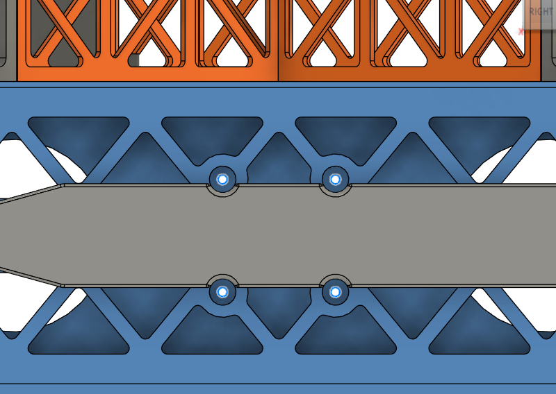
Step 1. Assemble the Cockpit Support Beams on Mid Plate
| Orientation | Rivet Holes |
|---|
 | 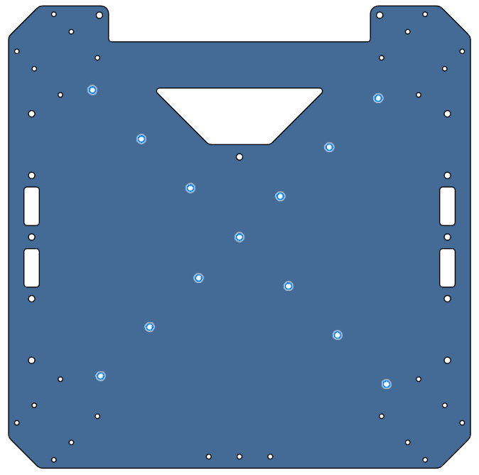 |
Step 2. Install the Battery Walls
- Parts needed:
- 1221 & 1222 (Battery Walls)
- Rivet 2 x10 (4mm Diameter for 2.5 mm - 4.5 mm thickness)
- Place the battery walls on the sides of the chassis as shown in the picture.
- Make sure the dented side stays on the chassis side.
- Rivet the battery walls from the mid plate on the holes shown in the picture.
| Orientation | Rivet Holes |
|---|
 |  |
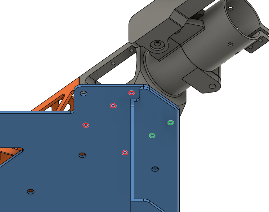
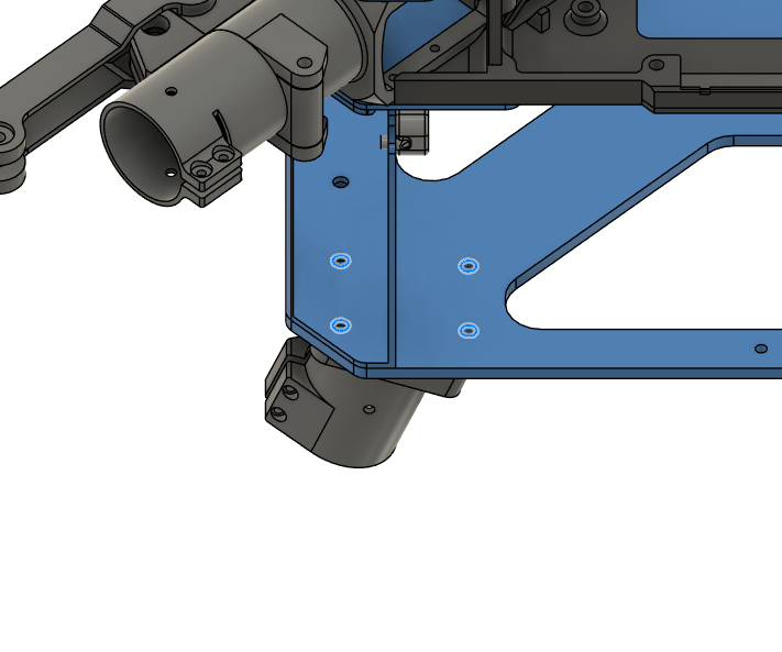
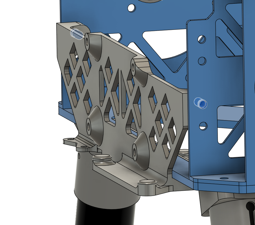
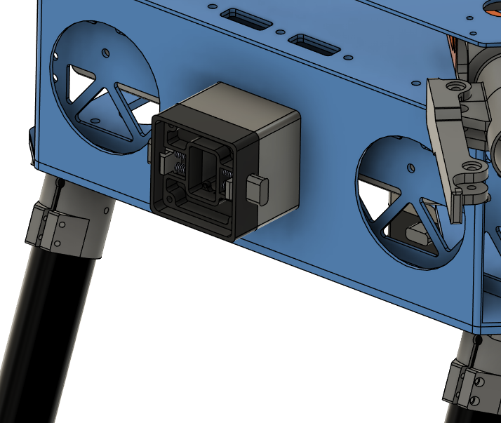
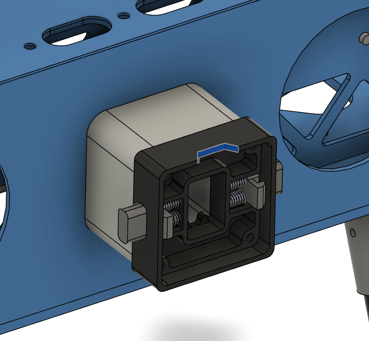
Step 3. Install the Motor Arm Connectors
| Motor Arm Connector - Loctite Threadlocker Application |
|---|
 |
- Place the motor arm connectors on the chassis as shown in the picture.
- Secure the motor arm connectors on the chassis.
- Use Screw 5 for red holes and Screw 1 for green holes.
- Use Loctite Threadlocker Blue.
- Use Washer 1.
- Use cordless screwdriver where possible, or else an allen key.
| Orientation | Screw Holes |
|---|
 |  |
Step 4. Install the Lower Plate
- Parts needed:
- 1113 (Lower Plate)
- Rivet 3 x10 (4mm Diameter for 4.5 mm - 6.4 mm thickness)
- Place the lower plate on the chassis as shown in the picture.
- Rivet the lower plate to the chassis on the holes shown in the picture.
| Orientation | Rivet Holes |
|---|
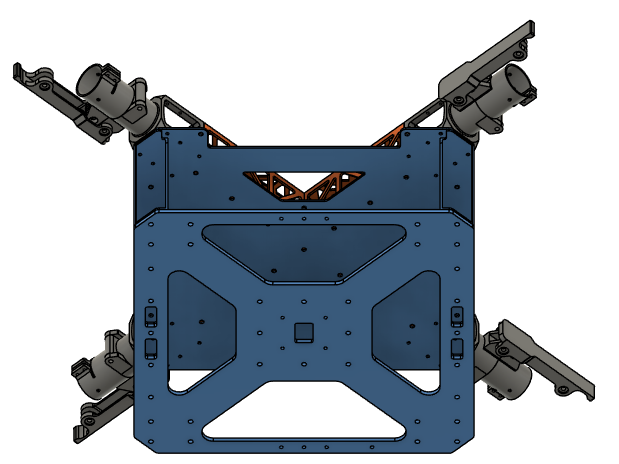 | 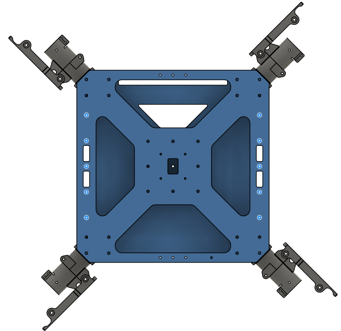 |
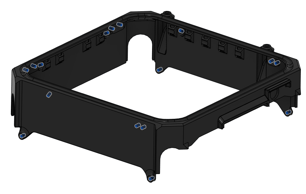
Step 5. Install the Upper Plate
-
Parts needed:
- 1111 (Upper Plate)
- Rivet 1 x13 (4mm Diameter for 1 mm - 2.5 mm thickness)
- Screw 5 x24 (Socket Head Screw M3x8)
- Washer 1 x24 (M3 General Purpose Washer 3.2 mm ID, 6 mm OD)
- Loctite Threadlocker Blue 242
-
Place the upper plate over the chassis as shown in the picture.
-
Rivet the cockpit support beams from the upper plate on the holes shown in the picture.
-
Screw the motor arm connectors from the upper plate with Screw 5.
- Use Washer 1.
- Use Loctite Threadlocker Blue.
| Orientation | Rivet Holes |
|---|
 |  |
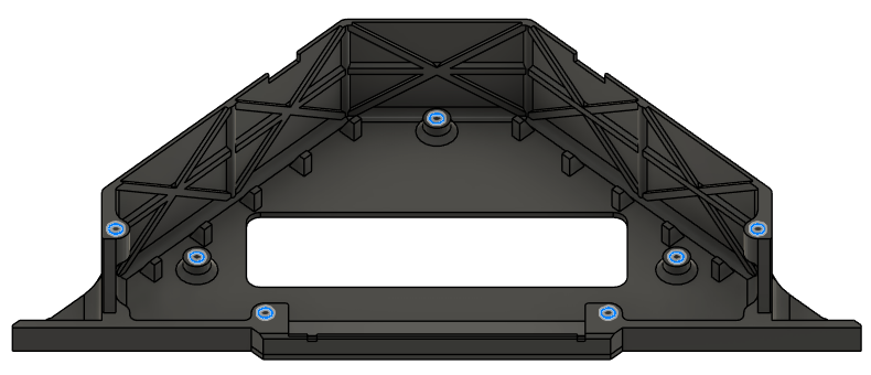
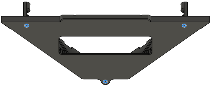
Step 6. Install the Main PCB Mount
| Top Insert Locations |
|---|
 |
- Install 5x Insert 4 into the bottom face of the Main PCB Mount (2311) as shown in the picture.
| Bottom Insert Locations |
|---|
 |
- Install 5x Vibration Mount into the designated holes on the Upper Plate (1111).
- Orientation: Ensure the longer side of the rubber dampener (3 mm section) is facing upwards, towards where the 3D-printed holder will sit.
| Vibration Mount Locations | Vibration Mount Insertion |
|---|
 |  |
- Apply a small amount of Loctite Threadlocker Blue to the threads of the 5x Screw 11 (M3x6) flat head screws.
- Align the 3D-printed mount over the rubber dampeners.
- Insert the Screw 11 (M3x6) screws through the center of the rubber dampeners and thread them into the bottom-side inserts of the PCB holder.
- Compression: Tighten the screws until the rubber dampener is compressed to a height of approximately 2.0 mm. Refer to the visual guide below.
| Vibration Mount Compression |
|---|
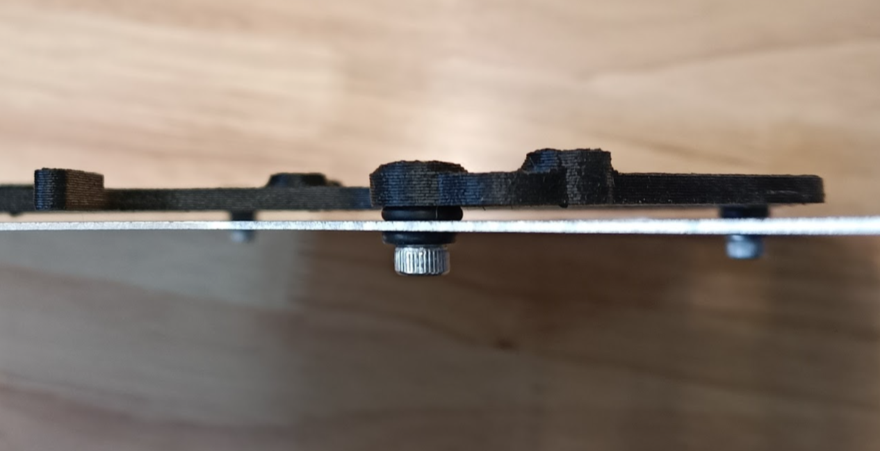 |
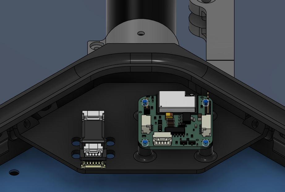
Step 7. Install the Battery Connector PCB Mount
| Top | Bottom |
|---|
 |  |
- Place the Battery Connector PCB mount over the mid plate.
- Secure it with 3x Screw 5 in total from below the mid plate on the holes below.
- Use Washer 1 for the holes.
Step 8. Install the Battery Sliders
- Place the battery sliders inside the battery compartment.
- Be careful about the orientation of the angled end, they should point where the cutouts on the plates are.
- Secure it with 8x Screw 9 in total from the sides of the frame.
- Use Washer 2 with the screws.
| Orientation | Installation Holes |
|---|
 |  |
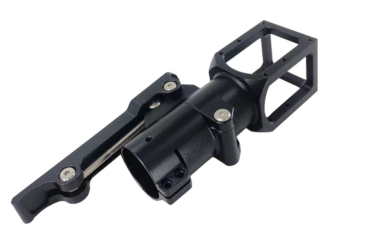
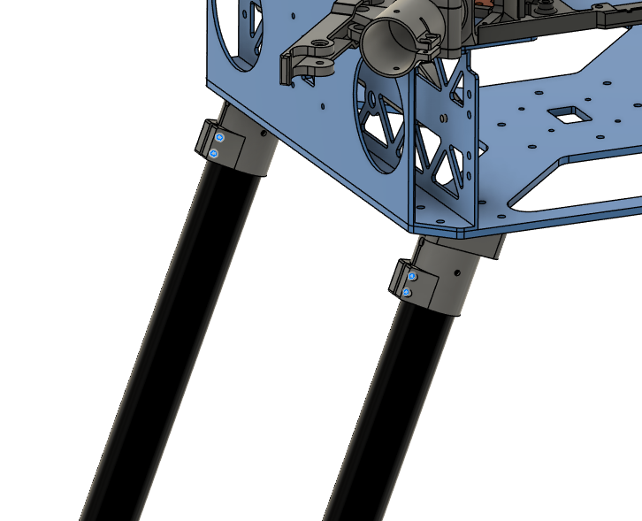
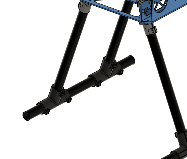
Step 9. Install the Landing Gear
| Orientation | Installation Holes |
|---|
 |  |
- Insert the vertical landing gear tubes inside landing gear main adapters.
- Make sure the tubes are inserted all the way.
- Tighten the clamps to secure the tubes in place.
Due to the lack of the detachable landing gear adapter geometry, this image depicts the old adapter. It should be updated with a real life image.
| Landing Gear Adapter |
|---|
 |
| Positioning | Correct Final Appearance |
|---|
 |  |
Due to the lack of the landing gear tee joint geometry, this image depicts the old joint. It should be updated with a real life image.
- Slide the landing gear foams to the end of the horizontal tubes.
Step 10. Install Sensor Mount
| Insert 1 (5.7 mm) Locations |
|---|
 |
 |
- Secure the sensor mount on the lower plate.
- Screw head stays inside the mount.
- Use Screw 4.
- Use Washer 1 on the nut side.
- Use Nut 1.
- DO NOT use Loctite Threadlocker.
| Lower Plate Fasteners |
|---|
 |
- Secure the sensor mount on the battery walls.
- Use Screw 5.
- Use Washer 1.
- Use Loctite Threadlocker Purple.
| Battery Wall Fasteners |
|---|
 |
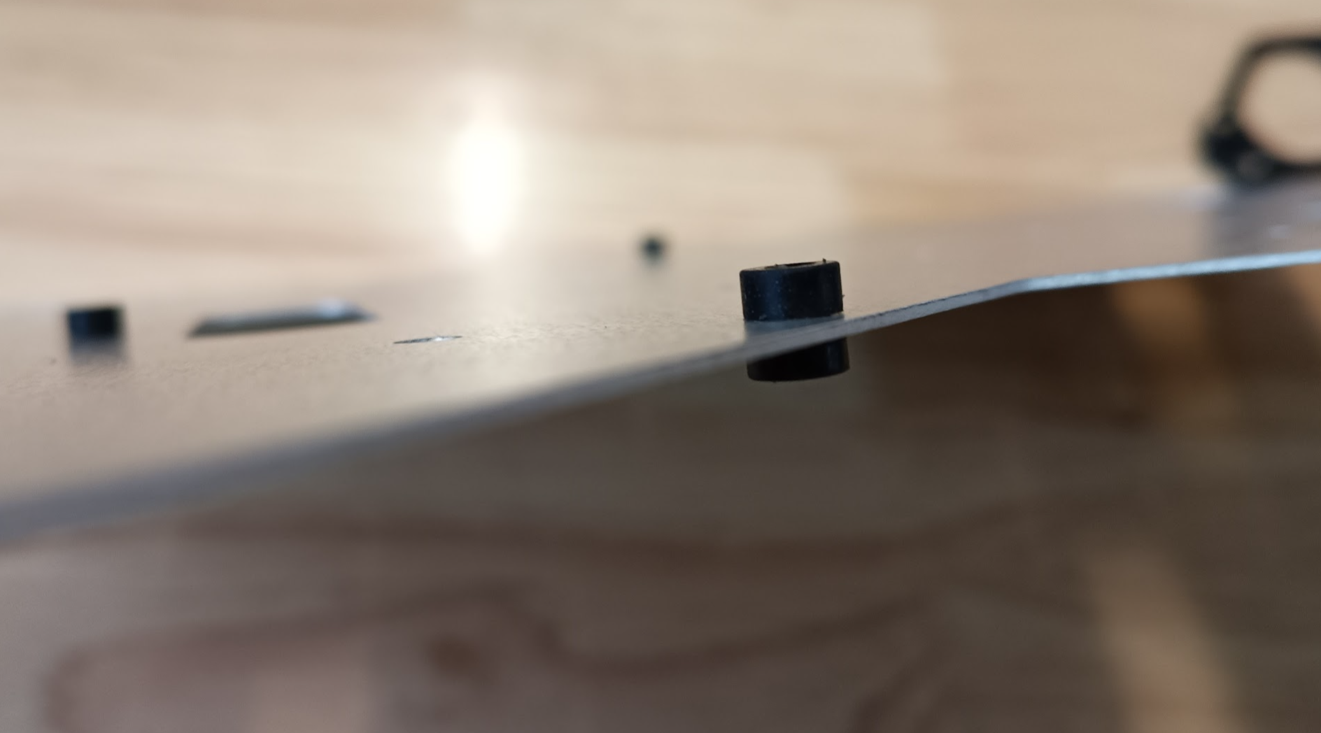
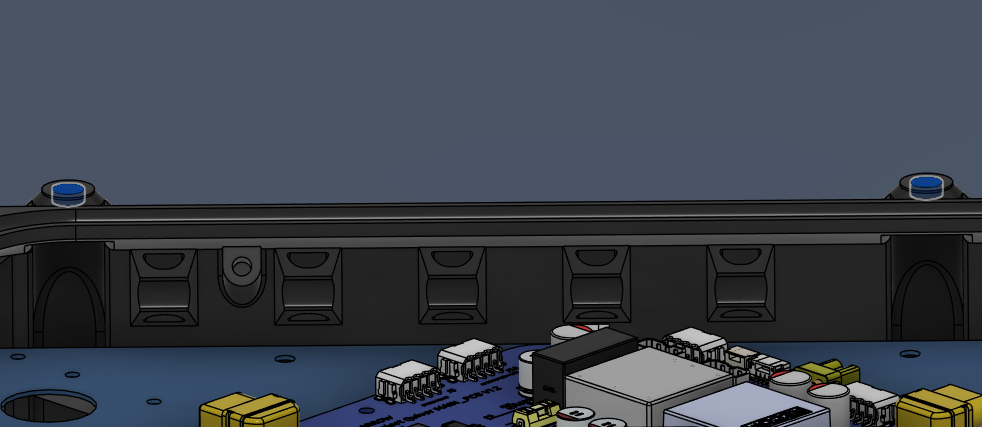
Step 11. Insert Grommets
| Grommet 1 Location |
|---|
 |
- Insert 12x Grommet 2 into the holes on the sides of upper, mid and lower plates on each side.
| Grommet 2 Location |
|---|
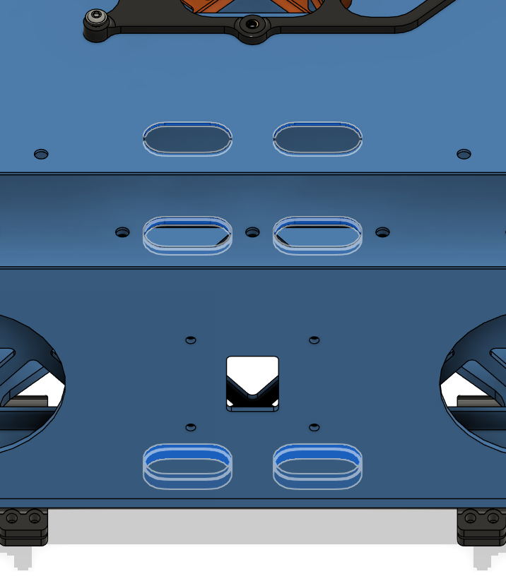 |
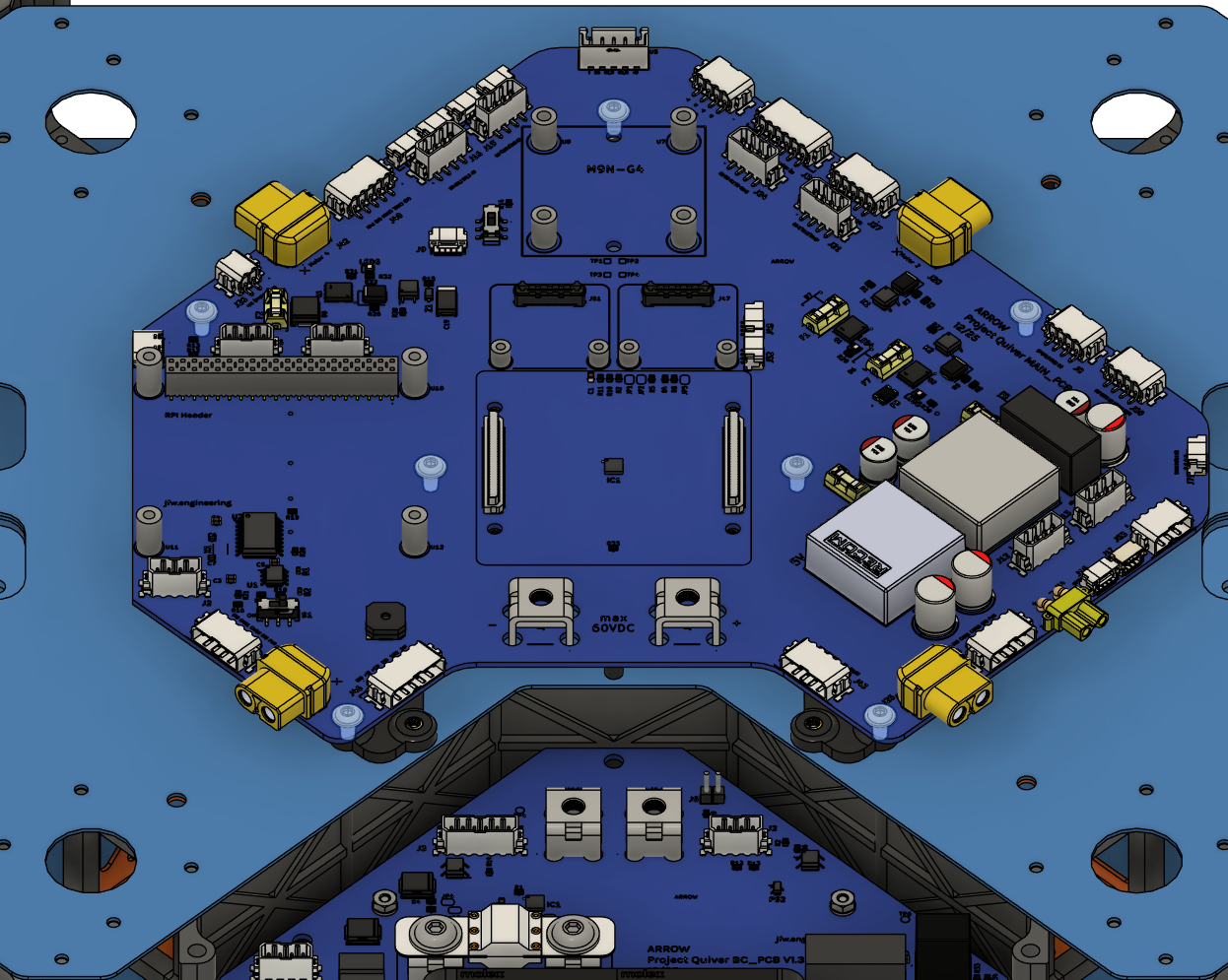
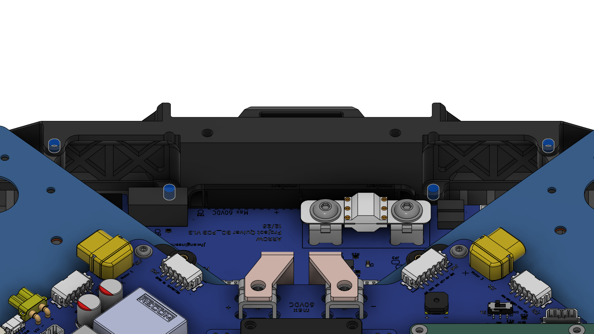
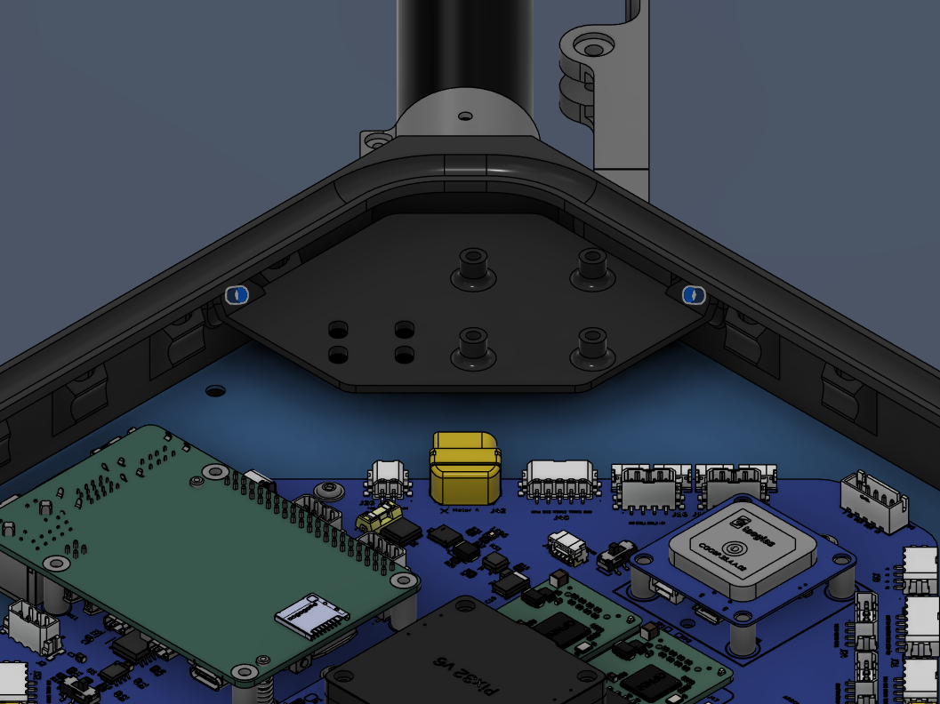
Step 12. Install PCBs & Onboard Components
| BC PCB & Bolt Locations |
|---|
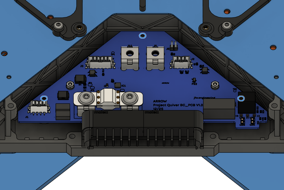 |
- Place the Main PCB as shown in the picture.
- See the warning before installation.
- Secure it with 7x Screw 11.
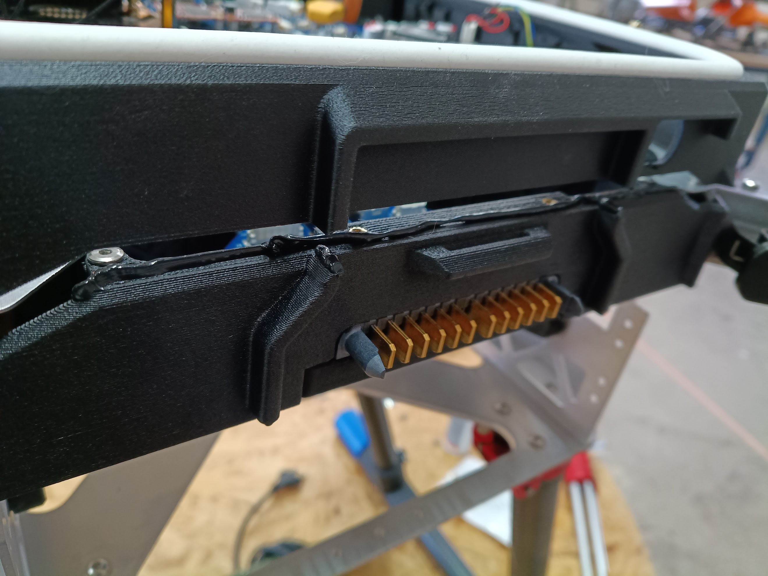
CRITICAL: Trim DC-DC Converter Pins
Before mounting the Main PCB, the through-hole pins of the DC-DC converters must be trimmed on the underside of the board. They extend too far and may puncture the mount or short against the frame.
See the reference image for the required clearance.
| Main PCB & Bolt Locations | Through-hole Pin Trim |
|---|
 | 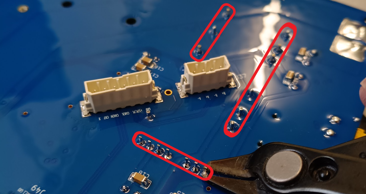 |
- Place Ethernet Switches on the Main PCB slots, as shown in the picture.
- Securely plug the connectors.
- Use 4x Screw 12 and 4x Washer 3 on the bolt holes.
- Use Loctite Threadlocker Purple.
| Ethernet Switch Locations |
|---|
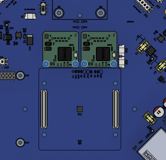 |
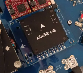
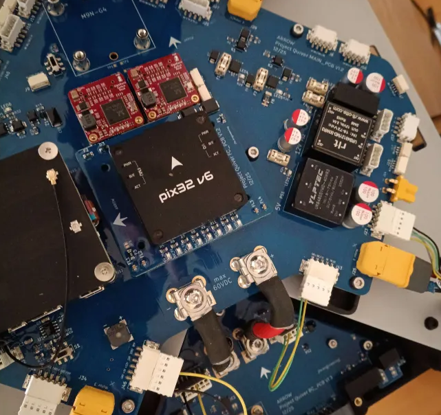
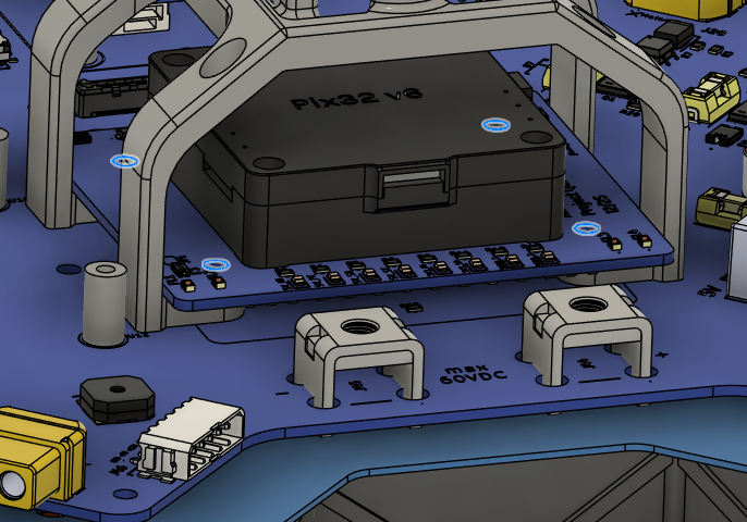
- Place the Flight Controller on the FC PCB.
- Pay extreme attention to the orientation shown in the images.
- Make sure the connectors are securely connected.
- Use 4x Screw 12 and 4x Washer 3 from under the PCB to secure the Flight Controller.
- Use Loctite Threadlocker Purple.
| FC & FC PCB Orientation | |
|---|
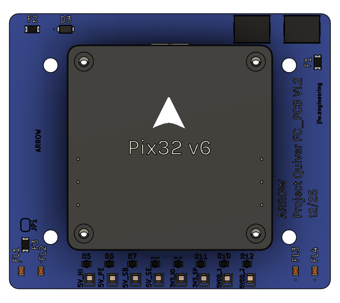 |  |
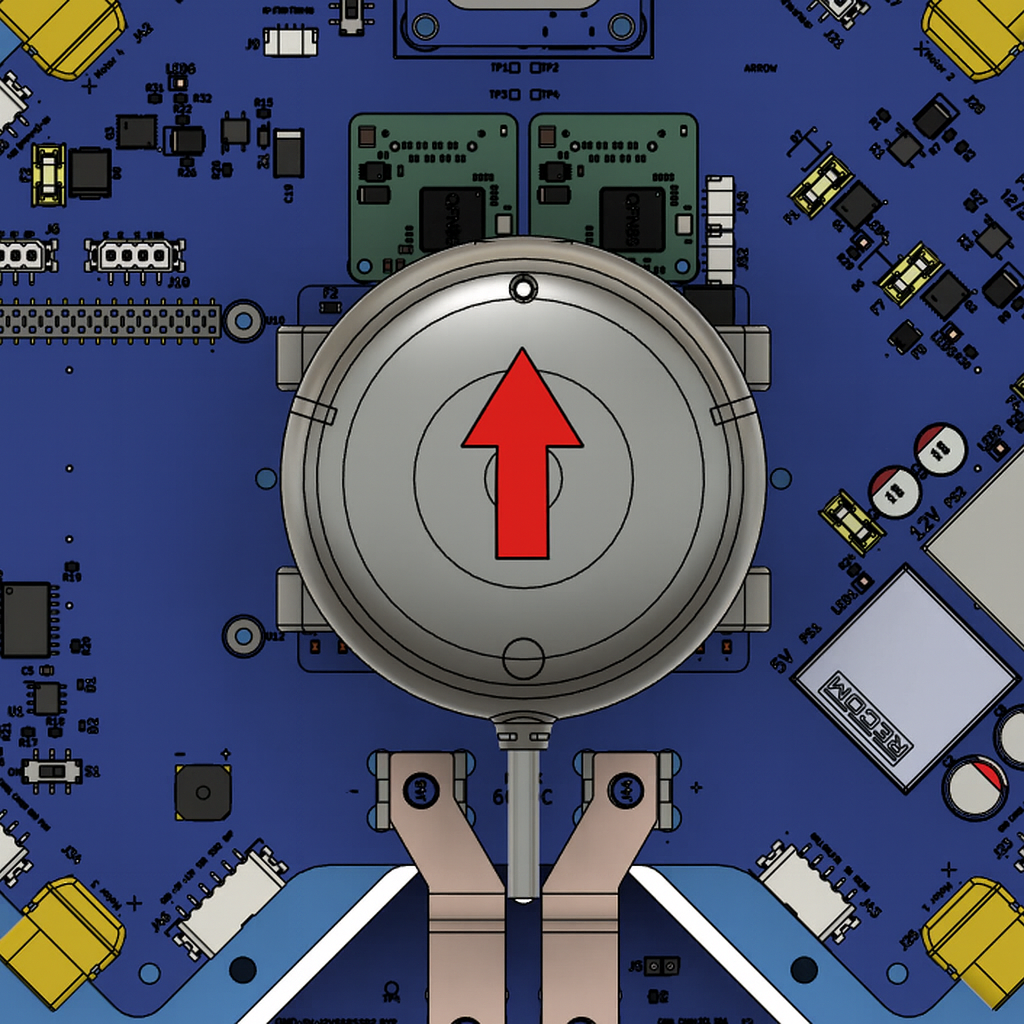
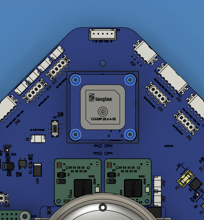
- Place F9P NEO RTK GNSS on the GNSS Mount.
- The direction of the arrow on the RTK GNSS should match the one provided in the picture.
- Secure it with Screw 14 and Washer 3 under the mount.
- Use Loctite Threadlocker Purple.
| GNSS Orientation |
|---|
 |
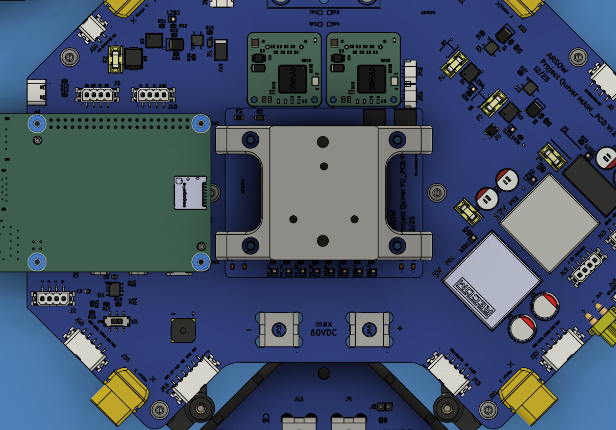
- Place the FC PCB into the GNSS Mount.
- Place the FC PCB and GNSS Mount on the Main PCB.
- The arrow on the Flight Controller must point toward the front of the drone, i.e., opposite to the side where the BC PCB is located.
- The arrow on the RTK GNSS must point toward the front of the drone, i.e., opposite to the side where the BC PCB is located.
- Secure the FC PCB on the Main PCB using the holes shown in the image.
- Use 4x Screw 4 and 4x Washer 5.
- Use Loctite Threadlocker Purple.
| Flight Controller Orientation | GNSS Mount Orientation | Installation Holes |
|---|
 |  |  |
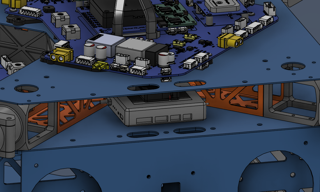
- Place RPI 5 on the Main PCB slot, as shown in the picture.
- Securely plug the connectors.
- Use 4x Screw 13 and 4x Washer 4 on the bolt holes.
| RPI 5 Installation |
|---|
 |
- Place Mateksys GNSS on the Main PCB slot, as shown in the picture.
- Securely plug the connectors.
- Use 4x Screw 11.
- Use Loctite Threadlocker Blue.
| Mateksys GNSS Installation |
|---|
 |
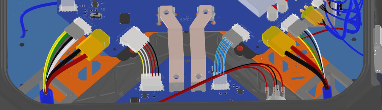
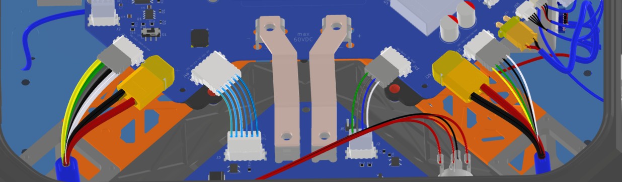
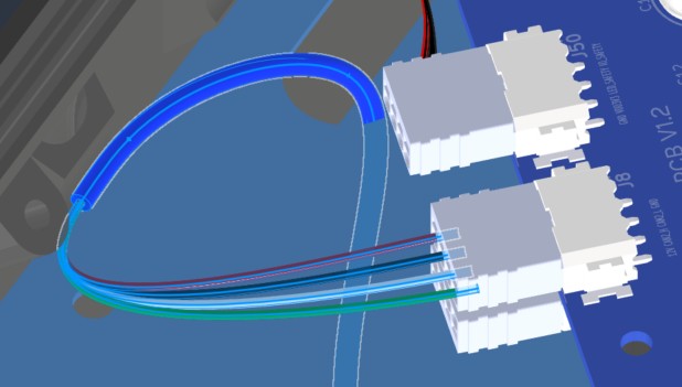
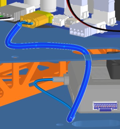
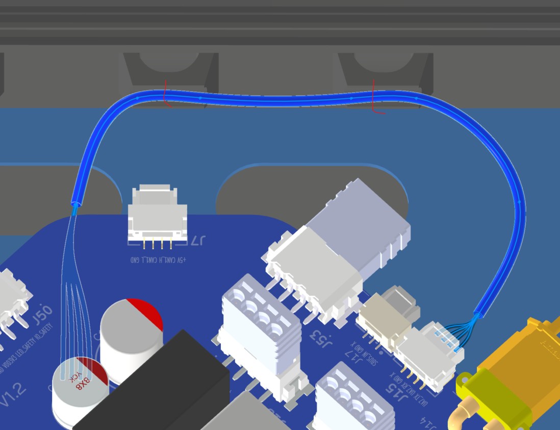
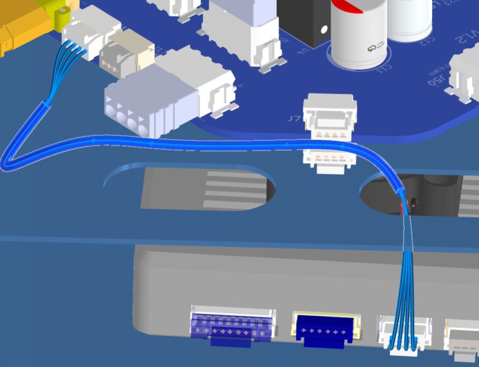
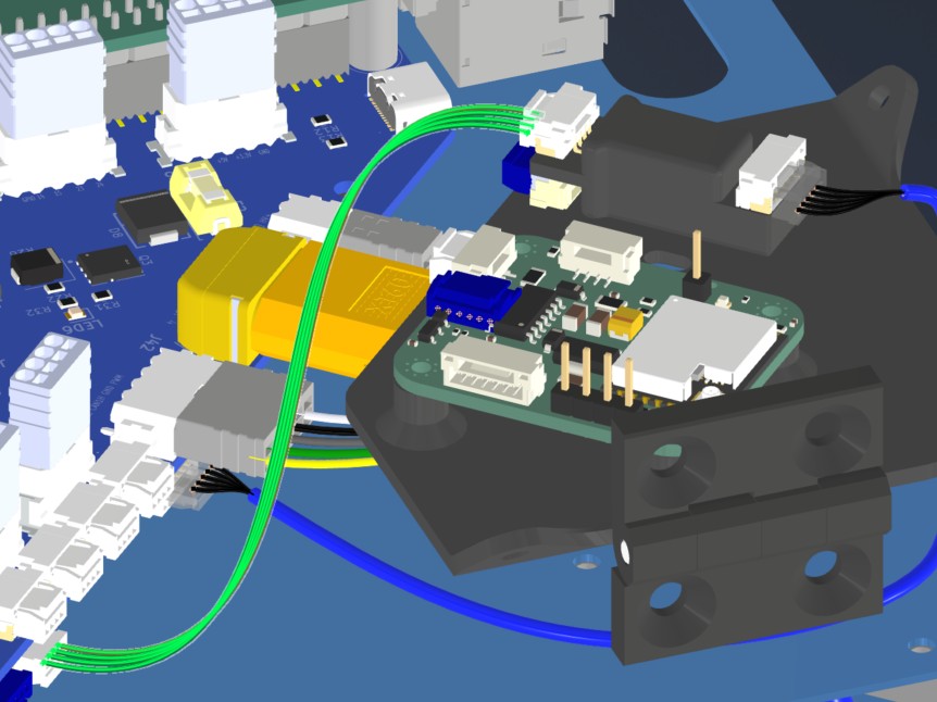
Harness Routing Notes
Route the PCB interconnect and navigation harnesses after the BC PCB, Main PCB, FC PCB, GNSS, and onboard components are mounted.
| Harness | Source | Destination | Routing notes |
|---|
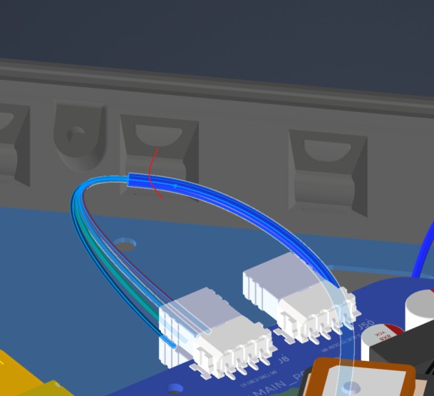
| HAR-0002 BC_PCB Signal | Bat_PCB J2 | Main_PCB J43 | Direct PCB interconnect. No special constraint or fixing noted. |
| HAR-0003 BC_PCB SSR | Bat_PCB J3 | Main_PCB J46 | Direct PCB interconnect. No special routing constraints currently noted. |
| HAR-0021 / HAR-0022 Navigation | Main_PCB J7, J9 | F9P/Here 4, Mateksys | Route immediately to the right. No special constraint or fixing noted. |
| HAR-0002 BC PCB Signal | HAR-0003 BC PCB SSR | HAR-0022 Navigation |
|---|
 |  |  |
Step 13. Install Busbars
| Busbar Installation |
|---|
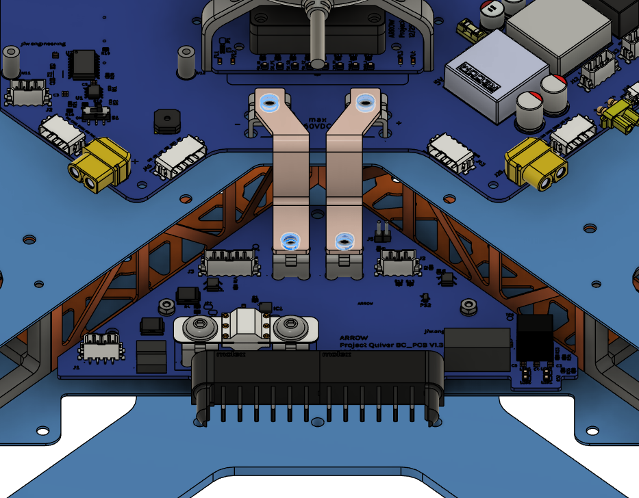 |
Step 14. Install BC PCB Cover
| Insert 1 Locations | Screw Locations |
|---|
 |  |
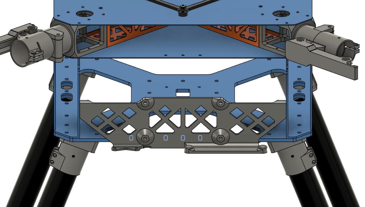
Step 15. Install Attachment Interfaces
| Positioning | Installation Holes | Notch Orientation |
|---|
 |  |  |
- Place and secure the bottom attachment interface and the spacer as shown in the pictures.
- Make sure the rectangular holes are aligned with the holes on the battery walls.
- Make sure the cable tray on the spacer points towards the front, i.e. the sensor mount.
- Make sure the notch on the attachment interface points towards the front, i.e. the sensor mount.
- Use 4x Screw 16.
- Use 4x Washer 1.
- Use Loctite Threadlocker Blue.
| Positioning, Cable & Notch Orientation | Installation Holes |
|---|
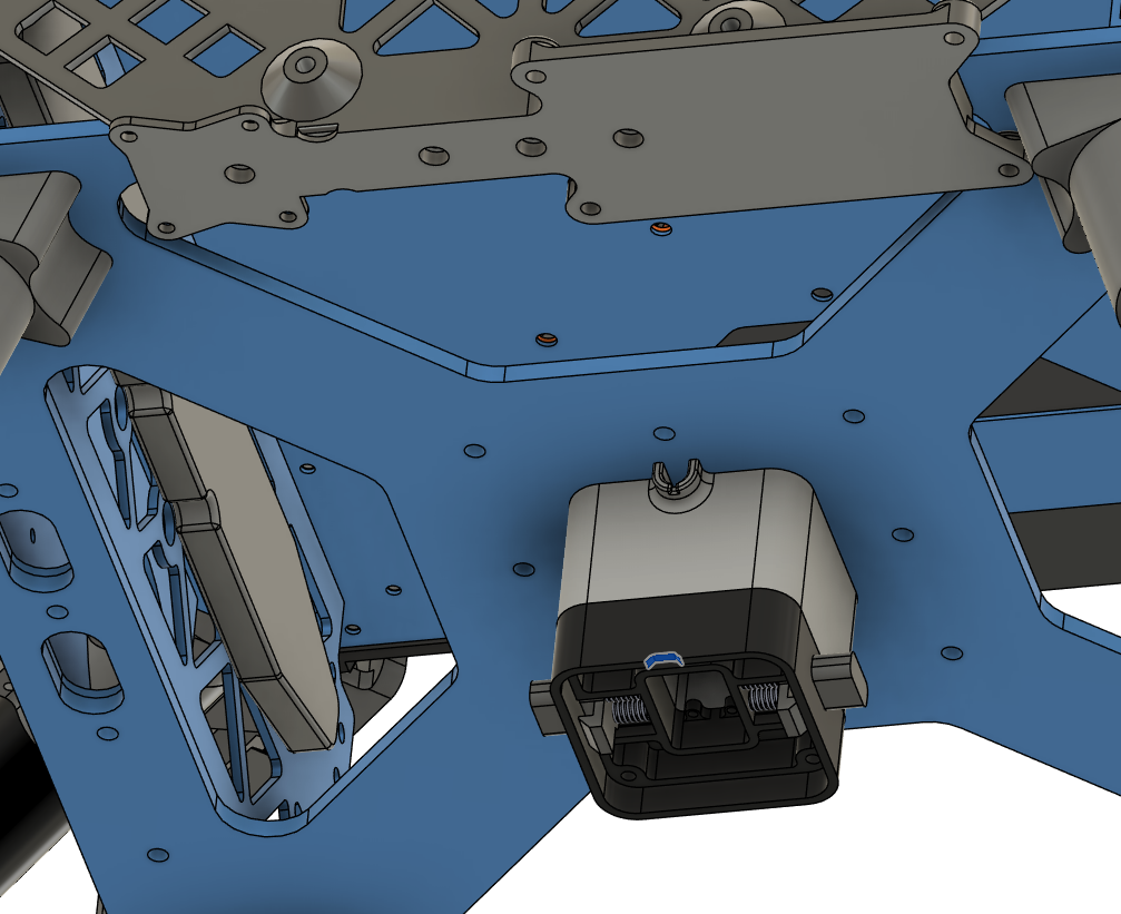 |  |
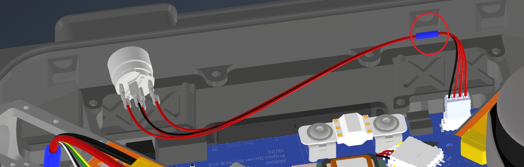
Step 16. Install Radar Sensors
| Obstacle Avoidance Installation |
|---|
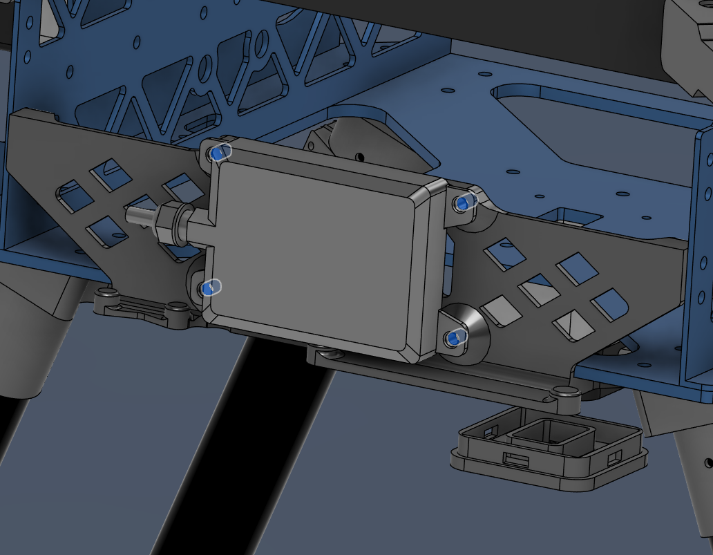 |
- Secure Nanoradar NRA15 in front-bottom corner of the drone, as shown in the image.
- Use 4x Screw 5.
- Use Loctite Threadlocker Purple.
- Mind the direction of the cable.
| Radar Altimeter Installation |
|---|
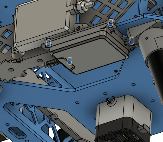 |
Harness Routing Notes
Route radar and altimeter harnesses while installing the sensors.
| Harness | Source | Destination | Routing notes |
|---|
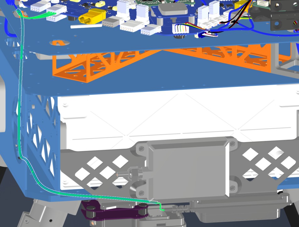
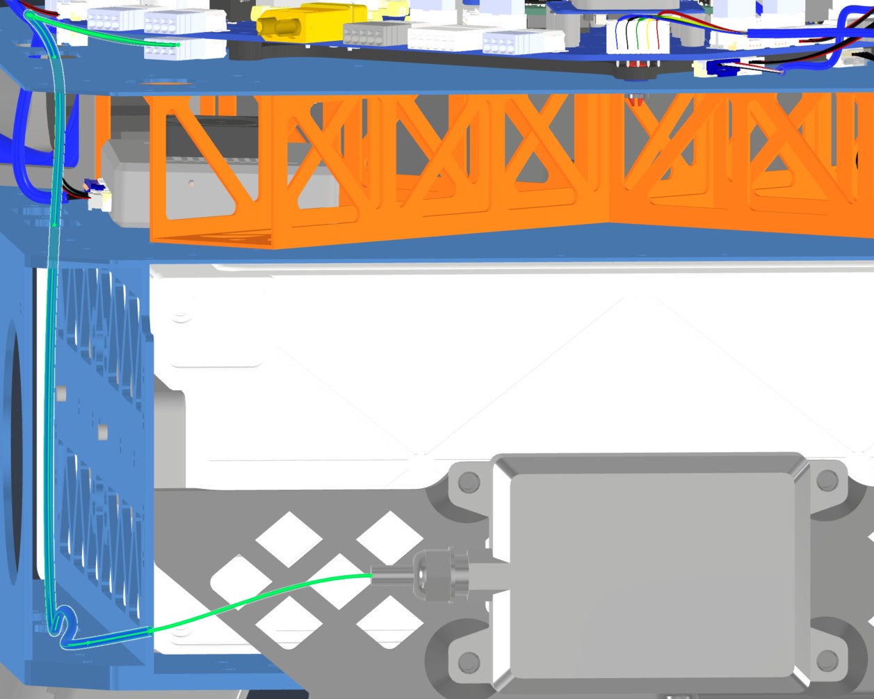
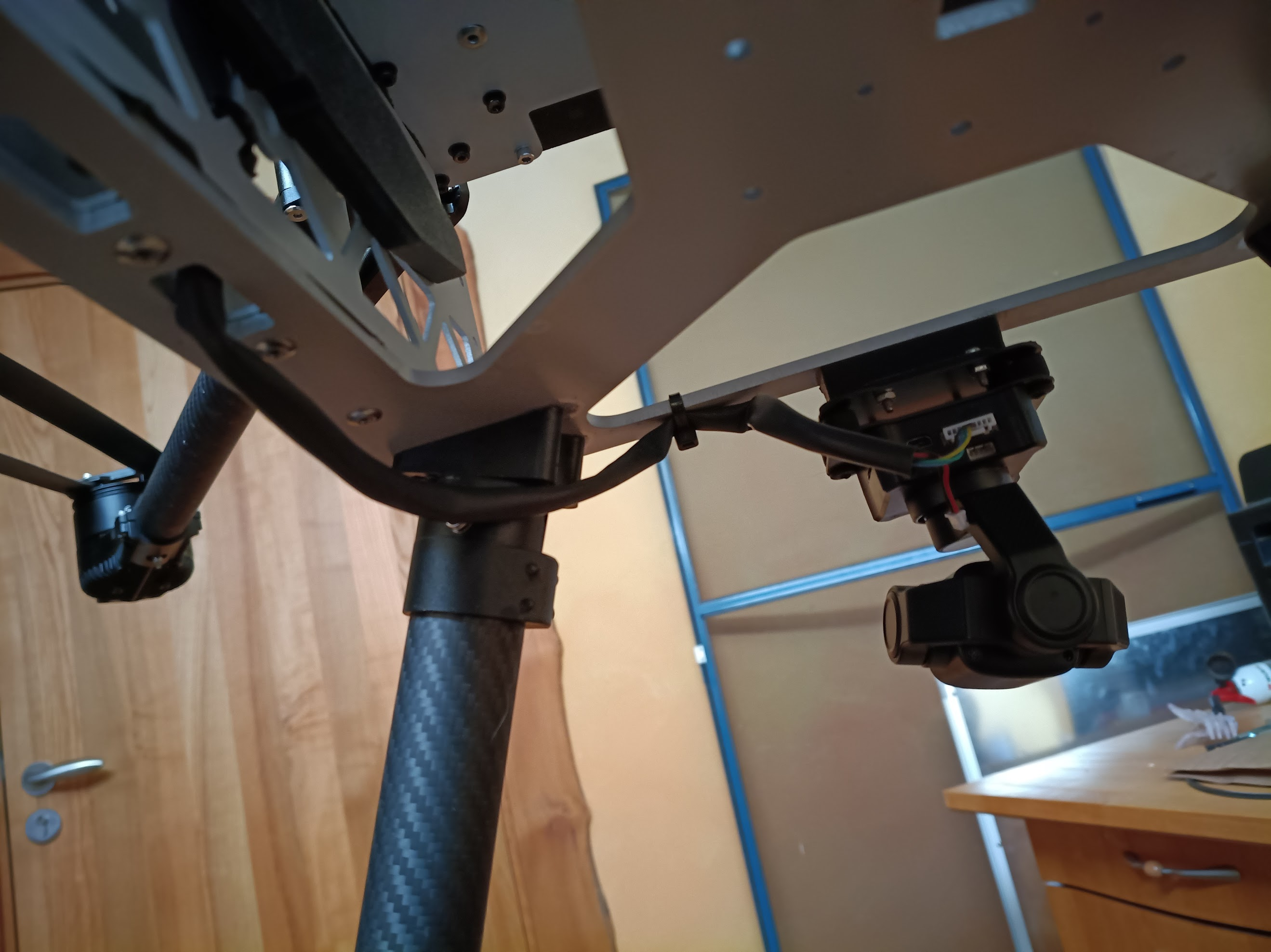
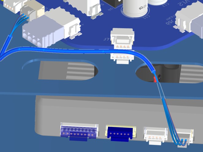
| HAR-0015 Altimeter | Main PCB J8 | NRA15 | Route from the right-side top-plate entry to the bottom plate. Watch other cables and fix with the marked zip tie. |
| HAR-0017 Front Radar | Main PCB J49 | Front radar | Route from the right-side top-plate entry to the bottom plate. Watch other cables and fix with the marked zip tie. |
| HAR-0015 Altimeter — View 1 | HAR-0015 Altimeter — View 2 |
|---|
 |  |
| HAR-0017 Front Radar — View 1 | HAR-0017 Front Radar — View 2 |
 |  |
Step 17. Install Camera
-
Parts needed:
- 3241 (SIYI A8 Mini Gimbal Camera)
- Screw 7 x4 (Socket Head Screw M2.5x6)
- Washer 4 x4 (M2.5 Nylon Washer 2.7 mm ID, 5.6 mm OD)
- Insert 5 x4 (M2.5 Threaded Inserts)
- Loctite Threadlocker Purple 222
-
Install 4x Insert 5 into the camera mounting holes on the drone.
-
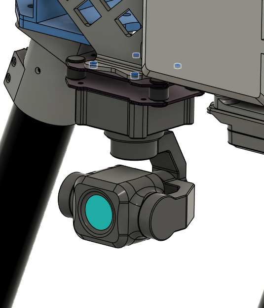
Secure SIYI A8 Mini Gimbal Camera in front-bottom corner of the drone, as shown in the image.
- Use 4x Screw 7.
- Use 4x Washer 4.
- Use Loctite Threadlocker Purple.
- Mind the orientation of the camera, make sure the gimbal center points forward, i.e. away from the drone.
| Camera Installation Holes | Camera Orientation |
|---|
 |  |
Harness Routing Notes
Route the camera harness while installing the SIYI camera.
| Harness | Source | Destination | Routing notes |
|---|
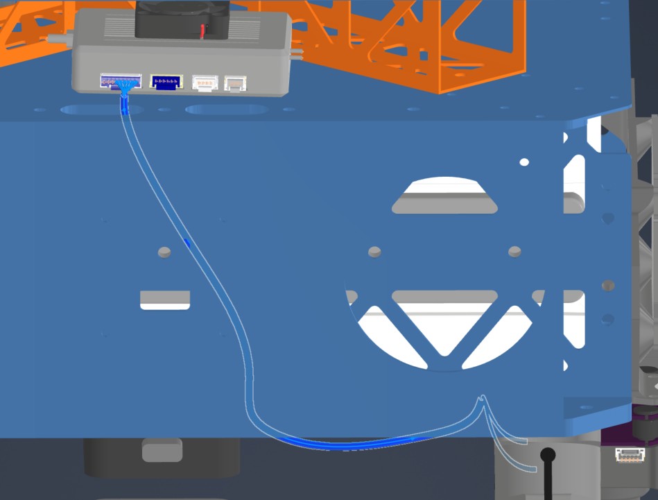
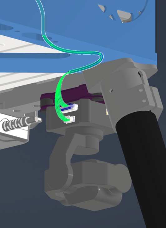
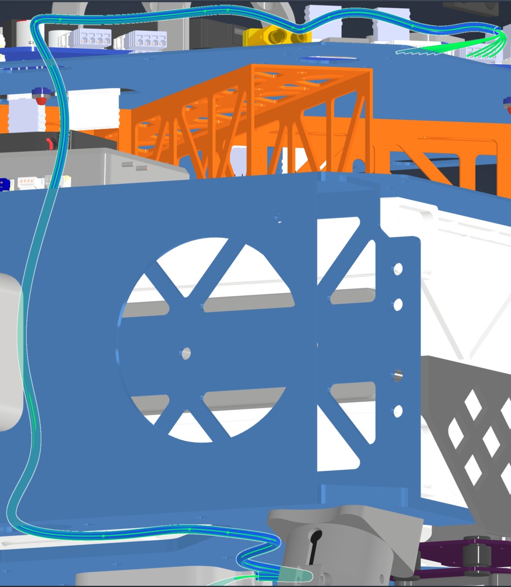
| HAR-0027 SIYI Camera | HM30 LAN and power | SIYI A8 | Route through the right-side middle-plate opening to the underside of the bottom plate. Watch other cables and use zip ties as needed. |
| HAR-0027 SIYI Camera — View 1 | HAR-0027 SIYI Camera — View 2 |
|---|
 |  |
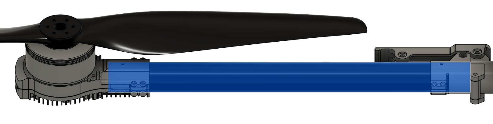
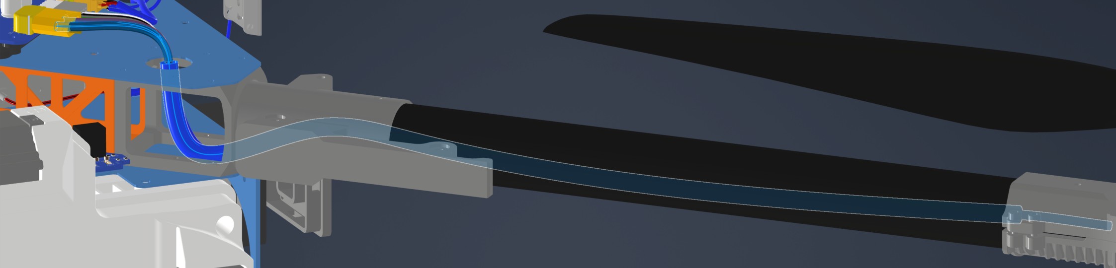
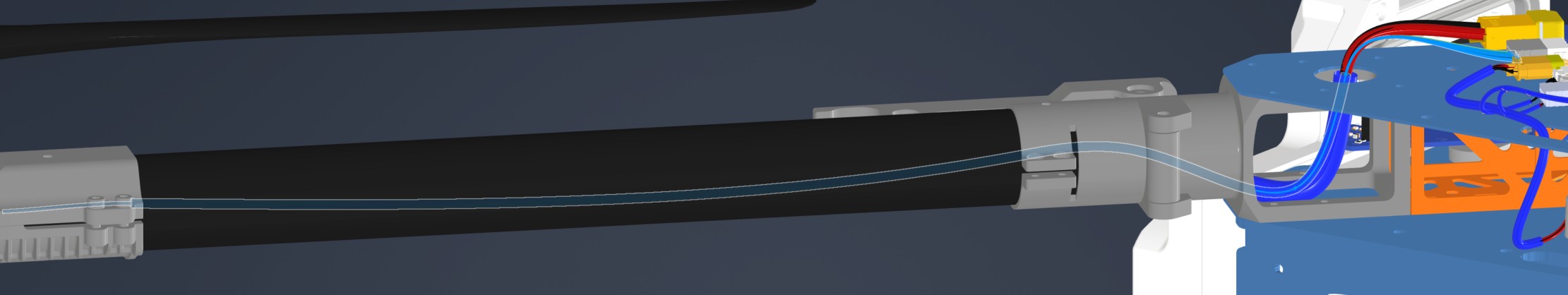
Step 18. Install Motor Arm Tubes & Motors
| Motor Arm Tube Hole Drilling Layout |
|---|
 |
-
Slide a tube inside each motor tube clamp.
- Orient the tube so that the motor is installed on the end with the shorter hole-to-end distance.
- Route the motor & ESC cables through the inside of the tube.
- Make sure the tubes are inserted all the way.
- Use Screw 6 to fix the tube in place.
- Use Washer 1 on each side.
- Use Nut 1.
- Do not apply more than 0.6 Nm of torque.
-
Tighten the clamps with the screws provided in the motor package.
-
Use Loctite Threadlocker Blue to secure the screws.
| Motor Installation |
|---|
 |
-
Install the motor arms on the motor arm connectors.
- Mind the motor spin directions. Use Ardupilot Quad X motor layout. See the image for reference. The front of the drone is where the radar sensors are.
- Make sure the tubes are inserted all the way.
- Route the cables from inside the tube, through the cable exit hole on top of the motor arm connector.
- Use Screw 6 to fix the tube in place.
- Use Washer 1 on each side.
- Use Nut 1.
- Do not apply more than 0.6 Nm of torque.
-
Tighten the clamps with the screws provided in the motor arm connector package.
-
Use Loctite Threadlocker Blue to secure the screws.
| Motor Arm Installation | Motor Cable Routing |
|---|
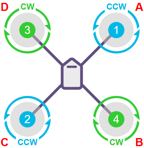 | 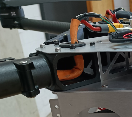 |
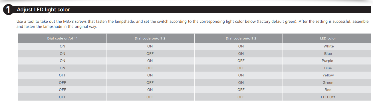
- Set the LED colors at each end of the motors.
- LEDs on the left side motors (Motors 2 & 3, C & D) should be RED.
- LEDs on the right side motors (Motors 1 & 4, A & B) should be GREEN.
- Use the motor user manual to set the colors.
| Adjusting LED Color Instructions |
|---|
 |
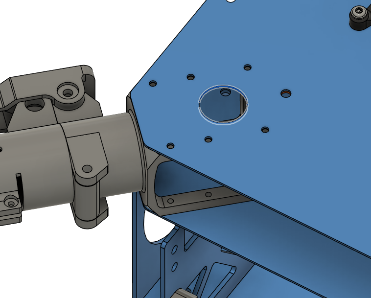
Harness Routing Notes
Route motor/ESC harnesses with the motor arms.
| Harness | Source | Destination | Routing notes |
|---|
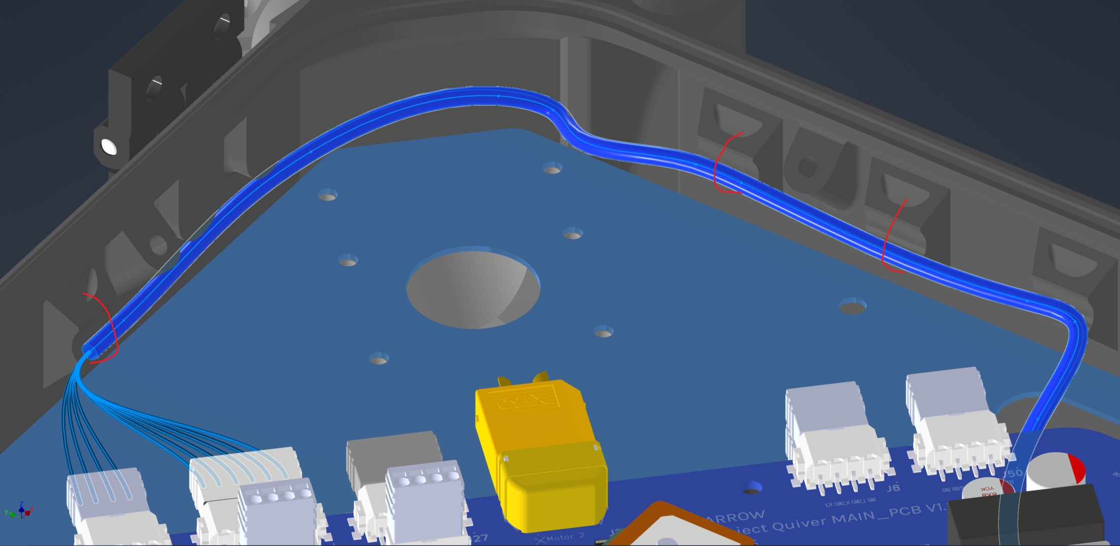
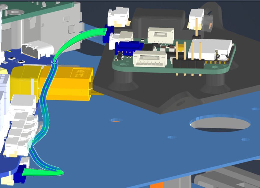
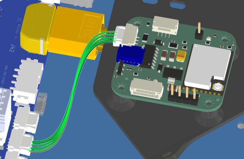
| HAR-0004 / HAR-0005 / HAR-0006 / HAR-0007 ESC Power | Main_PCB J27 | ESC power leads | Route through the circular hole on the upper plate to the middle plate. No special constraint or fixing noted. |
| HAR-0008 / HAR-0009 / HAR-0010 / HAR-0011 ESC Signal | Bat_PCB J2 | Main_PCB J43 | No special routing constraint or fixing currently noted. |
| HAR-0004 ESC Power | HAR-0008 ESC Signal |
|---|
 |  |
Step 19. Install Telemetry Air Unit & Attachment Interface PCBs
| HM30 Air Unit installation |
|---|
 |
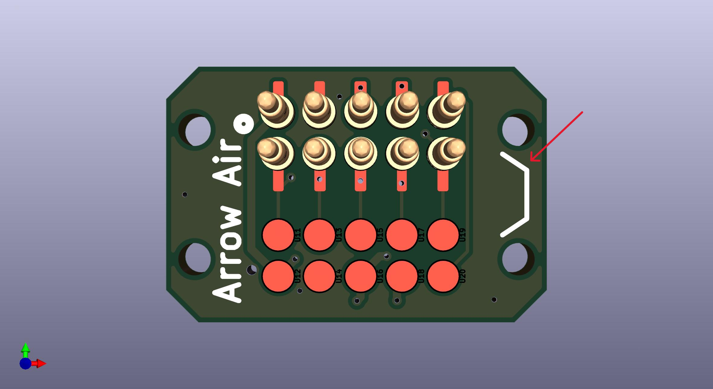
- Install the attachment interface PCBs on all three attachment interfaces.
- The pin side will face outward, while the connector side will stay inside.
- Make sure the side with the notch mark will be on the notch side of the attachment interface. (See Step 15 for notch reference)
- Secure them with Screw 3.
- Use Loctite Threadlocker Purple.
| Attachment Interface PCB Orientation | PCB Location |
|---|
 |  |
Harness Routing Notes
Route HM30 and attachment-interface harnesses while installing the telemetry air unit and attachment interface PCBs.
| Harness | Source | Destination | Routing notes |
|---|
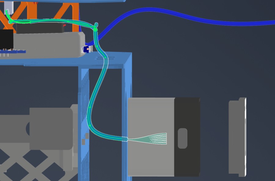
| HAR-0018 HM30 Power | Main_PCB J27 | HM30 power | Route through the right-side top-plate opening. No special constraint or fixing noted. |
| HAR-0019 / HAR-0020 HM30 Signal | Bat_PCB J15, J17 | HM30 | Route through the right-side top-plate opening. Watch other cables and secure with zip ties. |
| HAR-0012 / HAR-0013 Side Payloads | Main_PCB J29, J37 | ATT_INT right/left | Route underneath the Main PCB to the middle-plate side circular openings. Mirror the path for the opposite side. Watch the telemetry air unit location. |
| HAR-0014 Bottom Payload | Main_PCB J31, J39 | ATT_INT bottom | Route from the top plate through the right-side opening and mid-plate openings, then attach to the underside of the bottom plate. Watch the number of cables passing through openings. Fix with zip ties at the marked locations. |
| HAR-0018 HM30 Power | HAR-0019 HM30 Signal — View 1 |
|---|
 |  |
| HAR-0019 HM30 Signal — View 2 | HAR-0020 HM30 Signal |
 |  |
| HAR-0012 Side Payload | HAR-0014 Bottom Payload — View 1 | HAR-0014 Bottom Payload — View 2 |
|---|
 |  |  |
Step 20. Install Main Enclosure & Top Cap
| Insert 1 (5.7 mm) Locations |
|---|
 |
- Place Insert 1 to the holes shown in the picture on the top cap.
- Use a soldering iron to place them inside the plastic.
- 12 in total.
| Insert 1 (5.7 mm) Locations |
|---|
 |
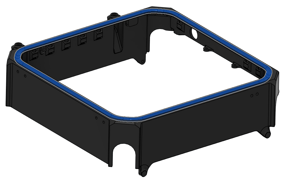
- Place Silicone Foam Seal Strip in the groove on the main enclosure.
- Cut the seal strip to length that minimizes the gap between the ends.
- Use Würth Super RTV Silicone Black to install it in the groove.
- Seal the gap between the ends of the strip with Würth Super RTV Silicone Black.
| Silicone Foam Seal Strip Location |
|---|
 |
- Install the hinges and latches on the main enclosure and the top cap.
- Use Screw 8 for the hinges.
- Use Screw 17 for the latches.
- Use Loctite Threadlocker Purple.
| Hinge & Latch Installation |
|---|
 |
- Place the main enclosure and the top cap on the aircraft.
- Apply Würth Super RTV Silicone Black on the contact surface between the BC-PCB cover and the main enclosure, as shown in the image.
- Make sure the antenna cables stay over the upper plate, as they will be hard to grab afterwards.
| Würth Super RTV Silicone Black Application |
|---|
 |
- Secure the main enclosure on each corner using the hole shown in the image.
- 4 locations in total.
- Use Screw 5.
- Use Washer 1.
- Use Loctite Threadlocker Purple.
| Main Enclosure Installation Hole |
|---|
 |
-
Parts needed:
- 3211 (Obstacle Avoidance Lidar S2L)
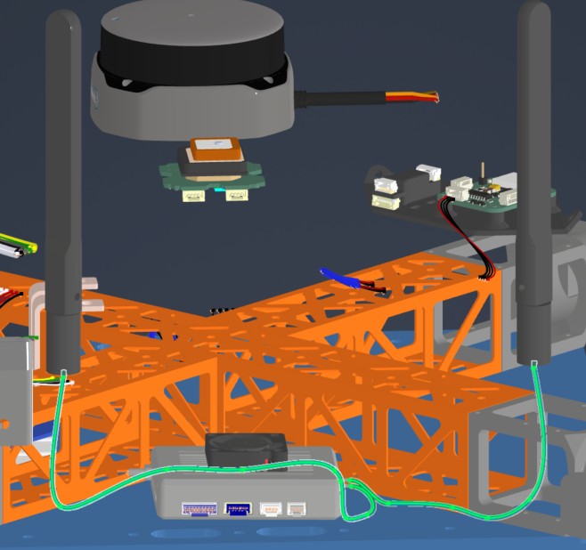
- 3221, 3222 (Front & Rear Telemetry Antennas)
- 3231 (Power Switch)
- Screw 5 x4 (Socket Head Screw M3x8)
- Washer 1 x4 (M3 General Purpose Washer 3.2 mm ID, 6 mm OD)
- Würth Super RTV Silicone Black
- Loctite Threadlocker Purple 222
-
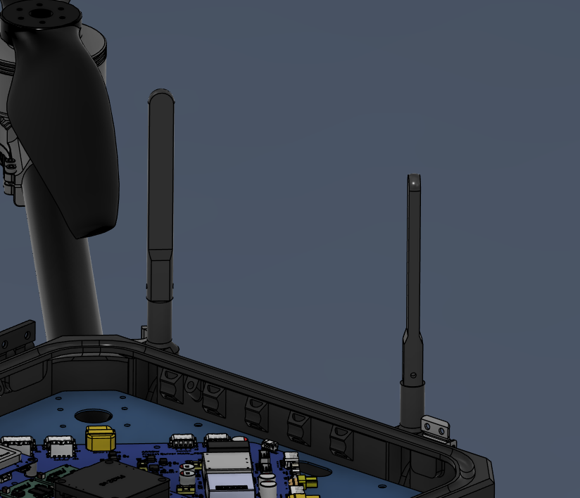
Remove the marked nuts from the antenna cables.
-
Insert the antenna cables through the holes shown in the picture.
-
Secure the antenna cables from outside with the nuts that were removed.
-
Install the antennas on the outside.
- Use a very small amount of Loctite Threadlocker Purple. Apply only to the threads near the base.
| Antenna Cable Nut | Antenna Cable Locations | Antenna Placement |
|---|
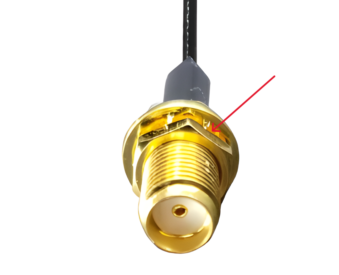 |  |  |
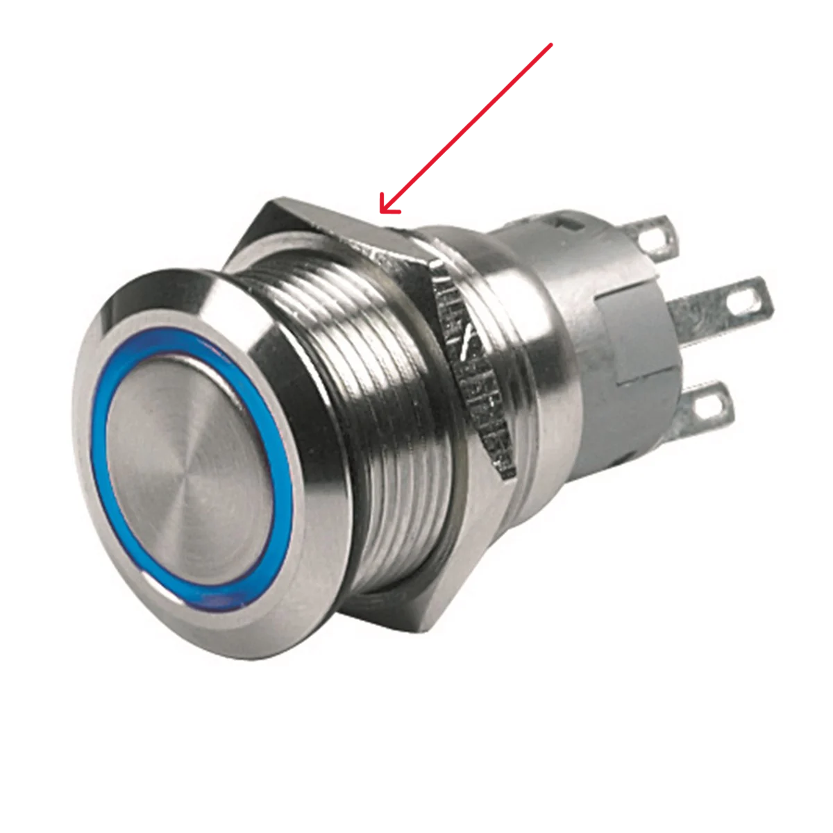
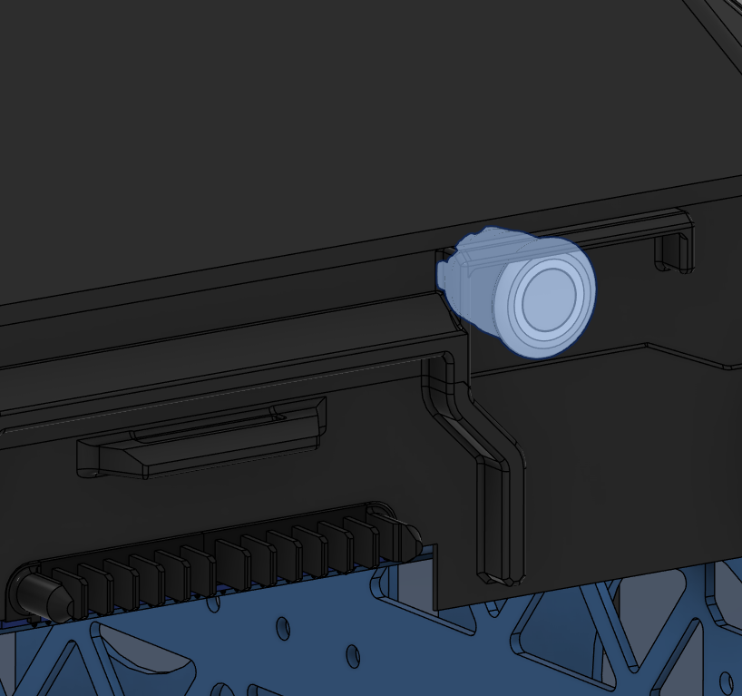
- Remove the marked nut from the push button.
- Insert the push button in its location on the main enclosure.
- Secure it with the nut from inside.
- Use Loctite Threadlocker Purple.
| Push Button Nut | Push Button Location |
|---|
 |  |
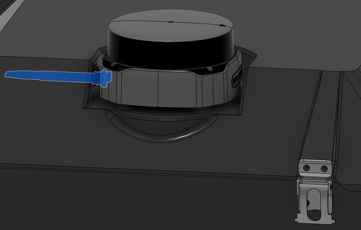
- Place the Lidar in its slot over the top cap.
- Mind the orientation of the cable. It should go through the hole on the top cap.
- Secure with Screw 5 and Washer 1.
- Use Loctite Threadlocker Purple.
- Seal the gap around the cable with Würth Super RTV Silicone Black.
| Lidar Installation |
|---|
 |
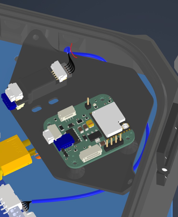
Harness Routing Notes
Route the pushbutton, LIDAR, and antenna harnesses while installing the enclosure-mounted components.
| Harness | Source | Destination | Routing notes |
|---|
| HAR-0001 Pushbutton | Bat_PCB J1 | Pushbutton | Route over the Battery PCB. Fix using the marked zip-tie provision. |
| HAR-0016 360 LIDAR | Main PCB U5 | S2L LIDAR | Route downward toward the connector and fix with the marked zip tie. |
| HAR-0028 Antenna | Antenna | HM30 | Route through the enclosure provisions to the middle plate. No special constraint or fixing noted. |
| HAR-0001 Pushbutton | HAR-0016 360 LIDAR | HAR-0028 Antenna |
|---|
 |  |  |
Step 22. Install the PPP Adapter & Beacon
| Insert 3 Locations |
|---|
 |
- Place the PPP Adapter & Beacon Mount inside the main enclosure, as shown in the picture.
- Secure it with Screw 5 and Washer 1.
- Use Loctite Threadlocker Purple.
| PPP Adapter & Beacon Mount Location |
|---|
 |
- Place the PPP Adapter & Beacon on the mount, as shown in the picture.
- Secure the Beacon with Screw 10, use Loctite Threadlocker Purple.
- Secure the PPP Adapter on the mount with double-sided tape.
| PPP Adapter & Beacon Mount Installation |
|---|
 |
Harness Routing Notes
Route PPP2ETH and Remote ID harnesses while installing the PPP adapter and beacon mount.
| Harness | Source | Destination | Routing notes |
|---|
| HAR-0023 / HAR-0024 / HAR-0025 PPP2ETH | Main_PCB J35, J36, J41 | PPP2ETH | Direct connections. HAR-0024 routes under the PPP/beacon mounting board; watch the mount and fix with the marked zip tie. |
| HAR-0026 Remote ID | Main_PCB J20 | Remote ID beacon | Direct connection. No special constraint or fixing noted. |
| HAR-0023 PPP2ETH | HAR-0024 PPP2ETH |
|---|
 |  |
| HAR-0025 PPP2ETH | HAR-0026 Remote ID |
 |  |