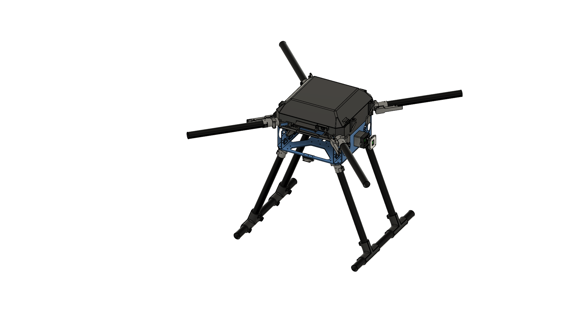
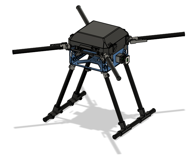
Project Quiver PT3 Structural Assembly Guide
BOM for the Assembly
Table 1. Structure parts
| Part ID | Part Name | CAD ID | Material | Sourcing | Quantity |
|---|---|---|---|---|---|
| 1 | Upper plate | 1101 | Aluminum | Laser Cut | 1 |
| 2 | Middle plate | 1102 | Aluminum | Laser Cut | 1 |
| 3 | Lower plate | 1103 | Aluminum | Laser Cut | 1 |
| 4 | Cockpit Support Beam CW Long | 1211 | Aluminum | Laser Cut | 1 |
| 5 | Cockpit Support Beam CCW Back | 1212 | Aluminum | Laser Cut | 1 |
| 6 | Cockpit Support Beam CCW Front | 1213 | Aluminum | Laser Cut | 1 |
| 7 | Battery Wall Left | 1221 | Aluminum | Laser Cut | 1 |
| 8 | Battery Wall Right | 1222 | Aluminum | Laser Cut | 1 |
| 9 | Foldable Motor Arm Connectors | 14X1 | Aluminum | Off-the-Shelf | 4 |
| 10 | Motor Arm Tubes | 14X2 | Carbon-Fiber | Cut-to-Length | 4 |
| 11 | Landing Gear Vertical Tubes | 1310 | Carbon-Fiber | Cut-to-Length | 4 |
| 12 | Landing Gear Horizontal Tubes | 1320 | Carbon-Fiber | Cut-to-Length | 2 |
| 13 | Landing Gear Main Adapters | 1330 | Aluminum | Off-the-Shelf | 4 |
| 14 | Enclosure Hinge | 2430 | Zinc | Off-the-Shelf | 2 |
| 15 | Landing Gear Tube Joints | 1340 | PETG-CF | 3D Print | 4 |
| 16 | Battery sliders | 2200 | PETG-CF | 3D Print | 2 |
| 17 | BC PCB Cover | 2313 | PETG-CF | 3D Print | 1 |
| 18 | Altitude Sensor Mount | 2330 | PETG-CF | 3D Print | 1 |
| 19 | Enclosure Anchors | 2420 | PETG-CF | 3D Print | 4 |
| 20 | Camera Mount | 2320 | PETG-CF | 3D Print | 1 |
| 21 | Attachment Interface Spacer Left | 2121 | PETG-CF | 3D Print | 1 |
| 22 | Attachment Interface Spacer Right | 2111 | PETG-CF | 3D Print | 1 |
| 23 | Attachment Interface Spacer Bottom | 2131 | PETG-CF | 3D Print | 1 |
| 24 | GNSS Mount Base | 2341 | PETG | 3D Print | 1 |
| 25 | GNSS Mount Clamp | 2342 | PETG | 3D Print | 1 |
| 26 | Main PCB Mount | 2311 | PETG | 3D Print | 1 |
| 27 | Main Enclosure | 2411 | PETG | 3D Print | 1 |
| 28 | Enclosure Top Cap | 2412 | PETG | 3D Print | 1 |
| 29 | Enclosure Cap Clips | 2440 | PETG | 3D Print | 4 |
| 30 | BC PCB Mount | 2312 | PETG | 3D Print | 1 |
| 31 | Attachment Interfaces | 2122 | Aluminum | Off-the-Shelf | 3 |
Table 2. Fasteners
| Fastener ID | Fastener Description | Quantity | McMaster-Carr Reference |
|---|---|---|---|
| Rivet 1 | 4mm Diameter for 2.5 mm - 4.5 mm thickness | 36 | 97525A251 |
| Rivet 2 | 4mm Diameter for 4.5 mm - 6.4 mm thickness | 10 | 97525A226 |
| Screw 1 | Socket Head Screw M3x10 | 48 | 91290A115 |
| Screw 2 | Flanged Button Head Screw M4x10 | 16 | 97654A373 |
| Screw 3 | Socket Head Screw M3x16 | 24 | 91292A115 |
| Screw 4 | Socket Head Screw M3x12 | 12 | 91290A117 |
| Screw 5 | Socket Head Screw M3x8 | 23 | 91290A113 |
| Screw 6 | Socket Head Screw M3x40 | 16 | 91290A136 |
| Screw 7 | Hex Drive Flat Head Screw M3x8 | 8 | 92125A128 |
| Screw 8 | Hex Drive Flat Head Screw M3x10 | 4 | 91294A130 |
| Screw 9 | Socket Head Screw M4x8 | 8 | 91290A140 |
| Screw 10 | Hex Drive Flat Head Screw M3x25 | 3 | 91294A138 |
| Insert 1 | M3 Threaded Inserts | 50 | 97163A161 |
| Insert 2 | M4 Threaded Inserts | 8 | 97163A153 |
| Washer 1 | General Purpose Washer 3.2 mm ID, 6 mm OD | 158 | 98689A112 |
| Washer 2 | General Purpose Washer 4.3 mm ID, 9 mm OD | 8 | 93475A230 |
| Nut 1 | Nylon-Insert Locknut M3 | 39 | 90576A811 |
Preparation
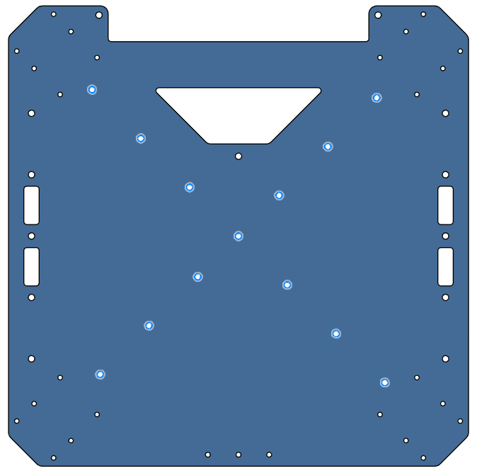
Parts 1-3
- All three are aluminum 6 series sheets, laser cut, sanded.
- Bounding box dimension is 300x300x2 mm for each.
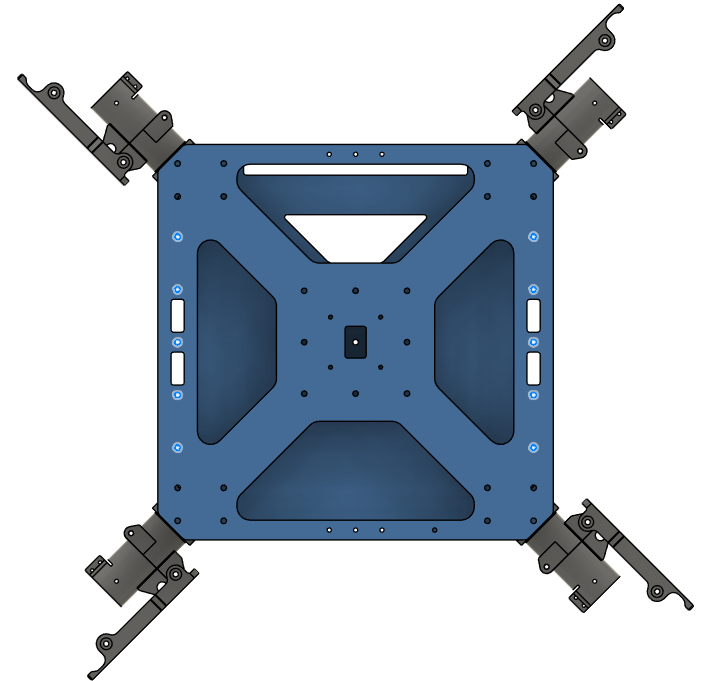
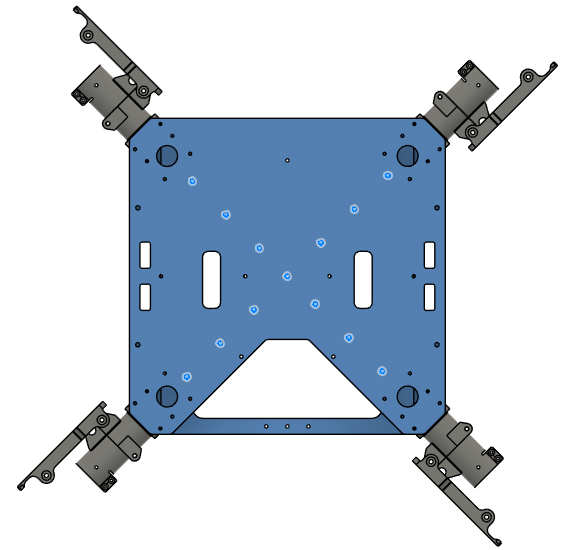
| Part 1 (Upper Plate) | Part 2 (Mid Plate) | Part 3 (Lower Plate) | |
|---|---|---|---|
| Thickness | 2 mm | 2 mm | 4 mm |
| Image | 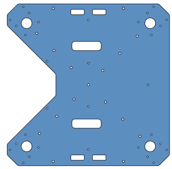 | 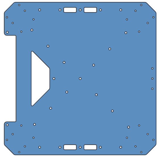 | 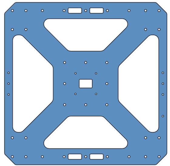 |
| CAD File | Part 1 | Part 2 | Part 3 |
Parts 4-6
- All three are aluminum 6 series, 40x40x2 mm square tubes, laser cut, sanded.
- Part 5 and Part 6 are identical, order 2 parts for the same geometry.
| Part 4 (Cockpit Support Beam CW Long) | Part 5 & 6 (Cockpit Support Beam CCW Back & Front) | |
|---|---|---|
| Length | 289.2 mm | 124.2 mm |
| Image | 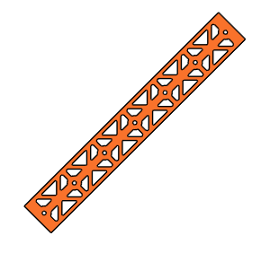 |  |
| CAD File | Part 4 | Part 5 & 6 |
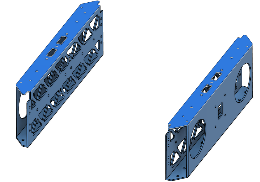
Parts 7-8
- Both are aluminum 6 series, 1000x30x2 mm rectangular tubes, laser cut, sanded.
- Length is 300 mm for each.
- Parts are identical, order 2 parts of the same geometry.
| Part 7 & 8 (Battery Wall Left & Right) | |
|---|---|
| Image | 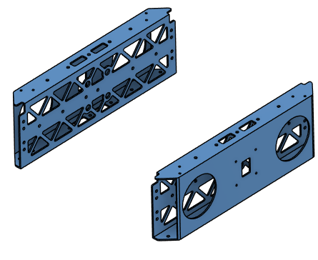 |
| CAD File | Part 7 & 8 |
Part 9
- Off-the-shelf component.
- 30 mm option.
- 4 parts in total.
- Product Link: Link
Parts 10-12
- 30x2 mm circular carbon-fiber tubes with different lengths.
- Reference link: Link
- Order 5 x 1000 mm or 10 x 500 mm
| Part 10 (Motor Arms) | Part 11 (Landing Leg Vertical Tubes) | Part 12 (Landing Leg Horizontal Tubes) | |
|---|---|---|---|
| Length | 360 mm | 400 mm | 500 mm |
| Quantity | 4 | 4 | 2 |
Part 13
- Off-the-shelf component.
- 30 mm option.
- 4 parts in total.
- Product Link: Link
Part 14
- Off-the-shelf component.
- Part Number: GN 237-ZD-30-30-A-SW
- 2 parts in total.
- Product Link: Link
Parts 15-23
- All 3D printed parts.
- They have structural roles on the airframe. Use PETG-CF filament.
- STL link: Parts 15-23
| Part | Quantity |
|---|---|
| Part 15 | 4 |
| Part 16 | 2 |
| Part 17 | 1 |
| Part 18 | 1 |
| Part 19 | 4 |
| Part 20 | 1 |
| Part 21 | 1 |
| Part 22 | 1 |
| Part 23 | 1 |
Parts 24-30
- All 3D printed parts.
- The parts should not interfere with GNSS signals. Use PETG filament.
- DO NOT use any filament containing carbon fiber.
- STL link: Parts 24-30
| Part | Quantity |
|---|---|
| Part 24 | 1 |
| Part 25 | 1 |
| Part 26 | 1 |
| Part 27 | 1 |
| Part 28 | 1 |
| Part 29 | 4 |
| Part 30 | 1 |
Part 31
- Off-the-shelf component.
- Order without PCB.
- 3 parts in total.
- Product Link: Link
Tool List
- You need the following tools:
- Allen key set
- Wrench set
- Cordless screwdriver or drill press
- Riveting tool
- Loctite Threadlocker Blue 242
- Adhesive: Loctite Superflex Silicon Sealant Model 593, 6.4 fl. oz.
- A cleaning agent to prepare the surfaces before adhesive
Assembly Steps
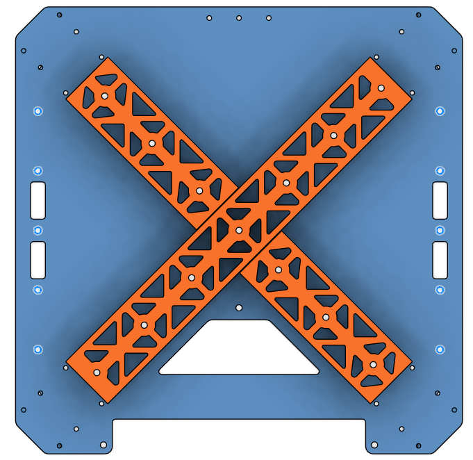
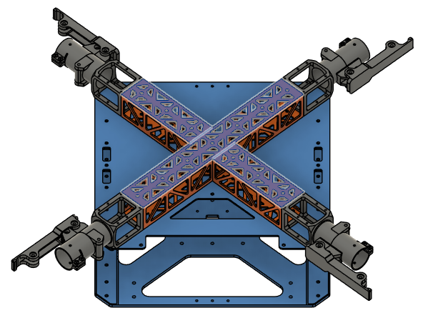
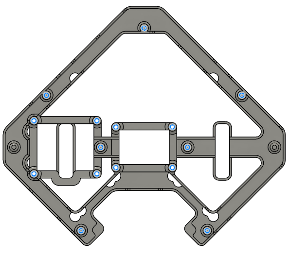
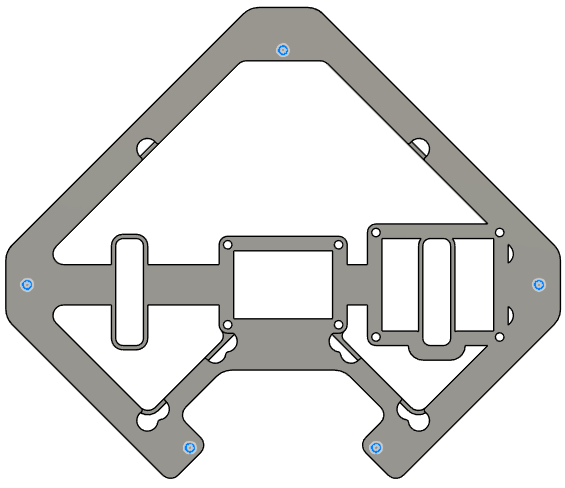
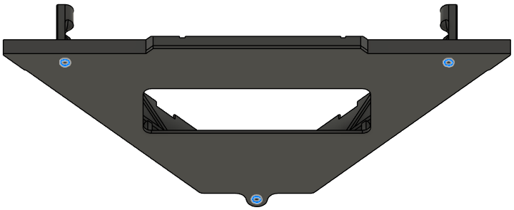
Step 1. Assemble the Cockpit Support Beams on Mid Plate
-
Parts needed:
- Part 2 (Mid Plate)
- Parts 4, 5, 6 (Cockpit Support Beams)
- Rivet 1 x13
-
Apply adhesive on the cockpit support beams around the holes on the contact side.
-
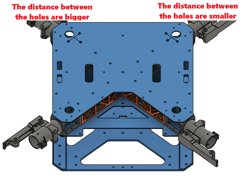
Place the cockpit support beams on the mid plate as shown to the picture.
-
Rivet the cockpit support beams from the mid plate on the holes shown in the picture.
- Make sure you rivet before the adhesive dries.
| Orientation | Adhesive Area | Rivet Holes |
|---|---|---|
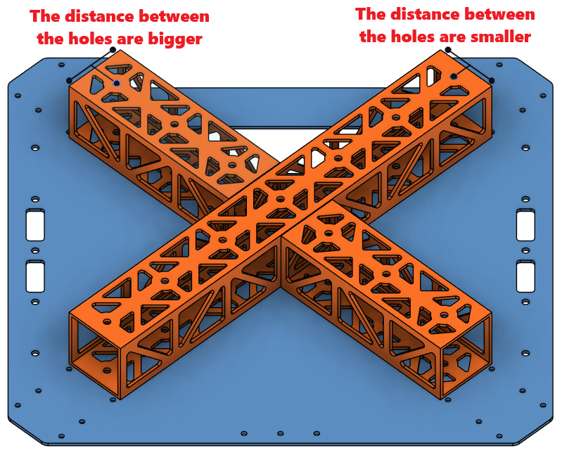 | 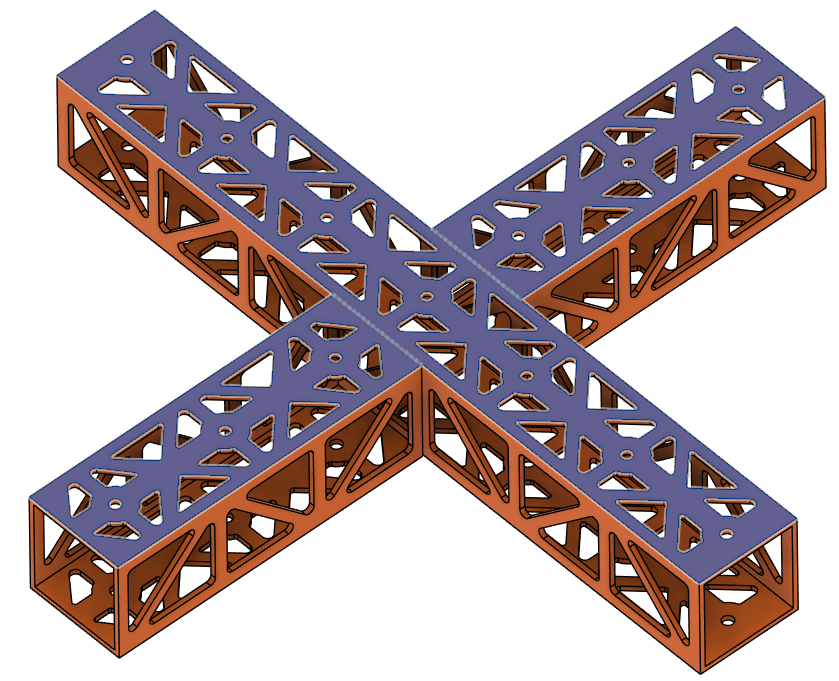 |  |
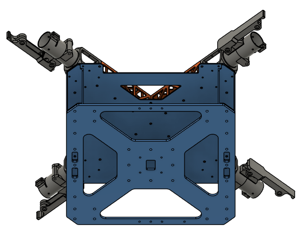
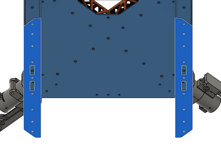
Step 2. Install the Battery Walls
- Parts needed:
- Step 1 chassis
- Parts 7, 8 (Battery Walls)
- Rivet 1 x10
- Apply adhesive on the battery walls around the holes on the contact side.
- Place the battery walls on the sides of the chassis as shown in the picture.
- Make sure the dented side stays on the chassis side.
- Rivet the battery walls from the mid plate on the holes shown in the picture.
- Make sure you rivet before the adhesive dries.
| Orientation | Adhesive Area | Rivet Holes |
|---|---|---|
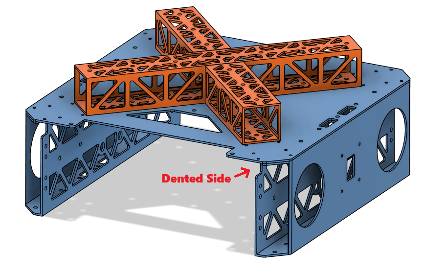 |  |  |
Step 3. Install the Motor Arm Connectors
- Parts needed:
- Step 2 chassis
- Part 9 x4 (Foldable Motor Arm Connectors)
- Screw 1 x16
- Screw 4 x8
- Washer 1 x24
- Place the motor arm connectors on the chassis as shown in the picture.
- Secure the motor arm connectors on the chassis.
- Use Screw 1 for red holes and Screw 4 for green holes.
- Use Loctite Threadlocker.
- Use Washer 1.
- Use cordless screwdriver where possible, or else an allen key.
| Orientation | Screw Holes |
|---|---|
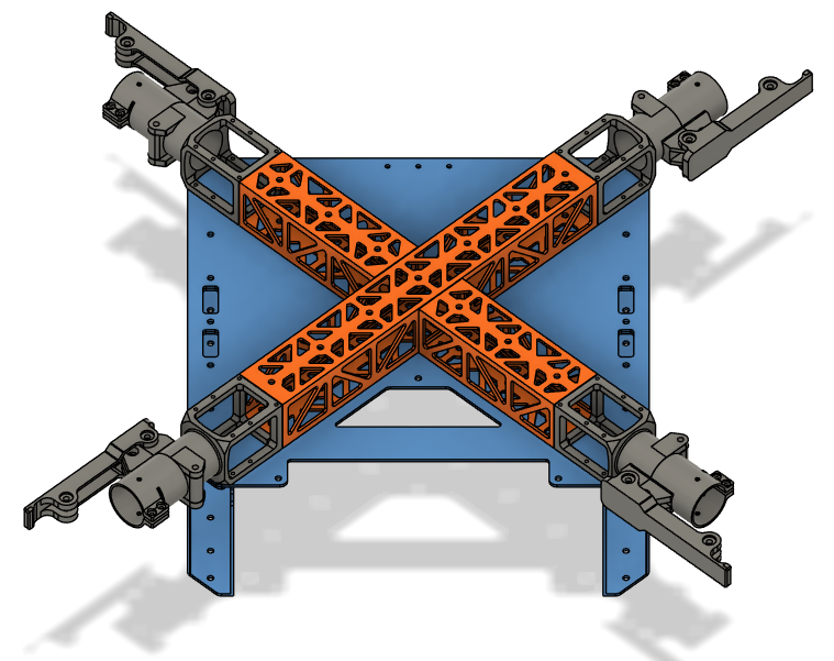 | 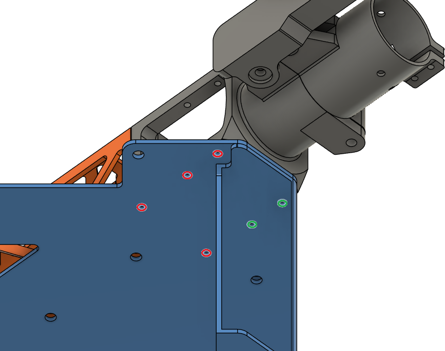 |
Step 4. Install the Lower Plate
- Parts needed:
- Step 3 chassis
- Part 3 (Lower Plate)
- Rivet 2 x10
- Place the lower plate on the chassis as shown to the picture.
- Apply adhesive on the battery walls around the holes on the contact side.
- Rivet the lower plate to the chassis on the holes shown in the picture.
- Make sure you rivet before the adhesive dries.
| Orientation | Adhesive Area | Rivet Holes |
|---|---|---|
 |  |  |
Step 5. Install the Upper Plate
-
Parts needed:
- Step 4 chassis
- Rivet 1 x13
- Screw 1 x24
- Washer 1 x24
-
Place the upper plate over the chassis as shown to the picture.
-
Apply adhesive on the cockpit support beams around the holes on the contact side.
-
Rivet the cockpit support beams from the upper plate on the holes shown in the picture.
- Make sure you rivet before the adhesive dries.
-
Screw the motor arm connecters from the upper plate with Screw 1.
- Use Washer 1.
- Use Loctite Threadlocker.
| Orientation | Adhesive Area | Rivet Holes |
|---|---|---|
 |  |  |
Step 6. Install the Battery Connector PCB Mount
-
Parts needed:
- Step 5 chassis
- Part 26 (Main PCB Mount)
- Insert 1 x20
- Screw 5 x20
- Washer 1 x20
-
Place Insert 1 to the holes shown in the picture, on the top and bottom sides of the main PCB mount.
- Use a soldering iron to place them inside the plastic.
| Top | Bottom |
|---|---|
 |  |
- Place the main PCB mount over the upper plate.
- Secure it with 5x Screw 5 in total from below the upper plate on the holes below.
- Use Washer 1 for the holes.
Step 7. Install the Main PCB Mount
-
Parts needed:
- Step 6 chassis
- Part 30 (BC PCB Mount)
- Insert 1 x10
- Screw 5 x3
- Washer 1 x3
-
Place Insert 1 to the holes shown in the picture, on the top and bottom sides of the BC PCB mount.
- Use a soldering iron to place them inside the plastic.
| Top | Bottom |
|---|---|
 |  |
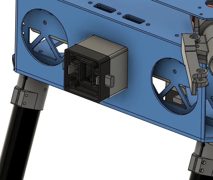
- Place the Battery Connector PCB mount over the mid plate.
- Secure it with 3x Screw 5 in total from below the mid plate on the holes below.
- Use Washer 1 for the holes.
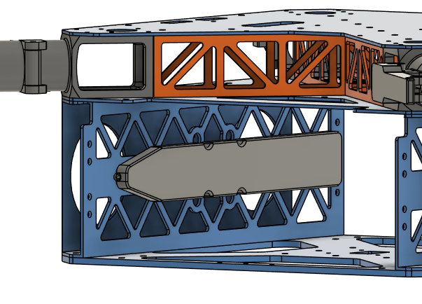
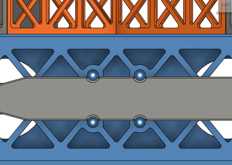
Step 8. Install the Battery Sliders
-
Parts needed:
- Step 7 chassis
- Part 16 (Battery Sliders)
- Insert 2 x8
- Screw 9 x8
- Washer 2 x8
-
Place Insert 2 to the holes shown in the picture on both of the battery slides.
- Use a soldering iron to place them inside the plastic.
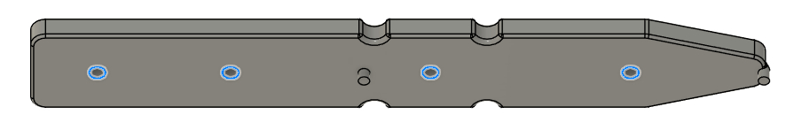
- Place the battery sliders inside the battery compartment.
- Be careful about the orientation of the angled end, they should point where the cutouts on the plates are.
- Secure it with 8x Screw 9 in total from the sides of the frame.
- Use Washer 2 with the screws.
| Orientation | Installation Holes |
|---|---|
 |  |
Step 9. Install the Landing Gear
- Parts needed:
- Step 8 chassis
- Part 11, 12 (Landing Gear Horizontal & Vertical Tubes)
- Part 13 (Landing Gear Main Adapters)
- Part 15 (Landing Gear Tube Joints)
- Screw 2 x16
- Screw 3 x24
- Washer 1 x56
- Nut 1 x28
- Screw 6 x4
- Place the landing gear main adapters below the chassis, as shown in the picture.
- The adapters are facing outside to the left and right of the structure.
- Screw the adapters with 16x Screw 2 to the chassis.
- Use Loctite Threadlocker to secure the screws.
| Orientation | Installation Holes |
|---|---|
 |  |
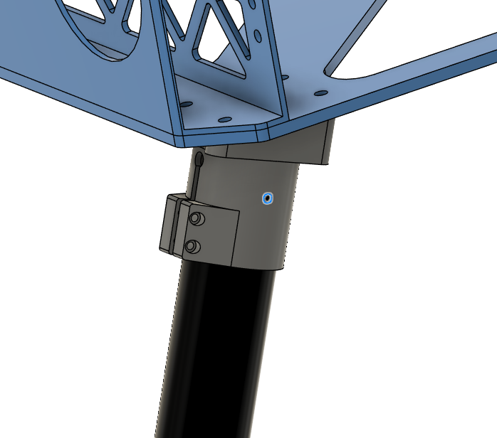
- Insert the vertical landing gear tubes inside landing gear main adapters.
- Make sure the tubes are inserted all the way.
- Tighten the clamps with the screws provided in the landing gear main adapter package.
- Use Loctite Threadlocker to secure the screws.
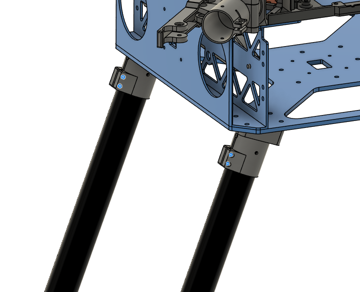
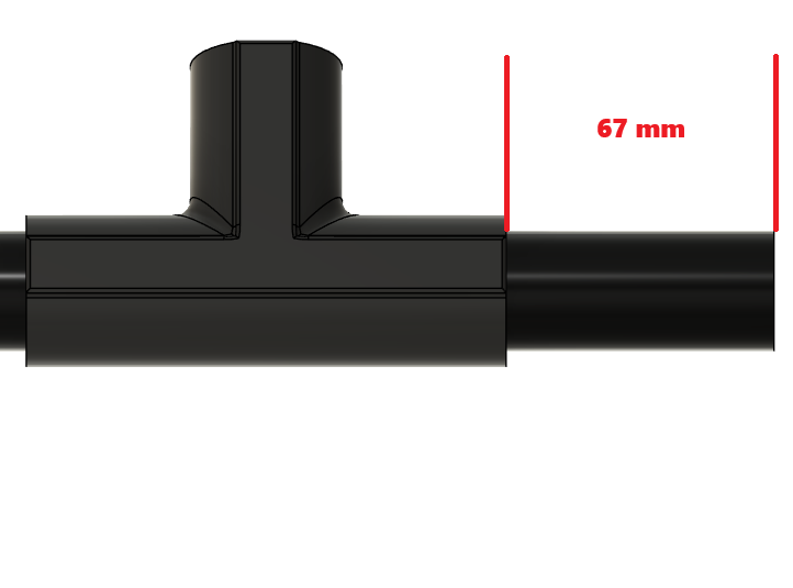
-
Make sure the chassis stands level on the ground.
- If not, measure and equalize the tube lengths.
-
Drill the tubes with 3 mm drill bit on the marked holes.
- Use Screw 6.
- Use Washer 1 on each side.
- Use Nut 1.
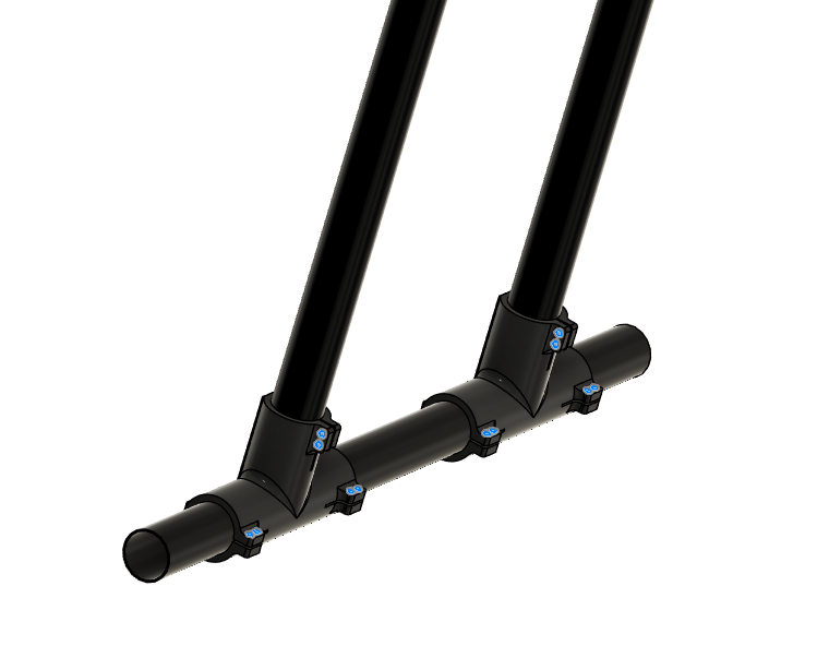
- Assemble landing gear tube joints and the horizontal tubes as shown in the picture.
- Insert the vertical tubes inside the holes before tightening the screws.
- Use Screw 3.
- Use Washer 1 on each side.
- Use Nut 1.
| Positioning | Installation Holes |
|---|---|
 |  |
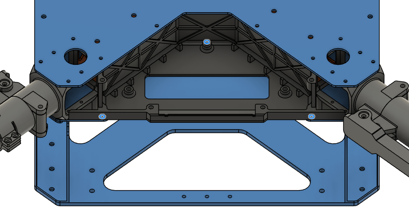
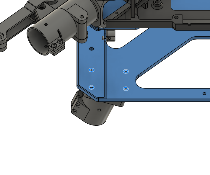
Step 10. Install Side Attachment Interfaces
-
Parts needed:
- Step 9 chassis
- Part 21, 22 (Side Attachment Interface Spacers)
- Part 31 (Attachment Interfaces)
- Screw 6 x8
- Washer 1 x8
-
Place and secure side attachment interfaces and the spacers as shown in the pictures.
- Make sure the rectangular holes are aligned with the holes on the battery walls.
- Use the screwdriver holes inside the battery compartment to place the screws and the screwdriver.
- Use Screw 6.
- Use Washer 1.
- Use Loctite Threadlocker.
| Positioning | Installation Holes |
|---|---|
 |  |
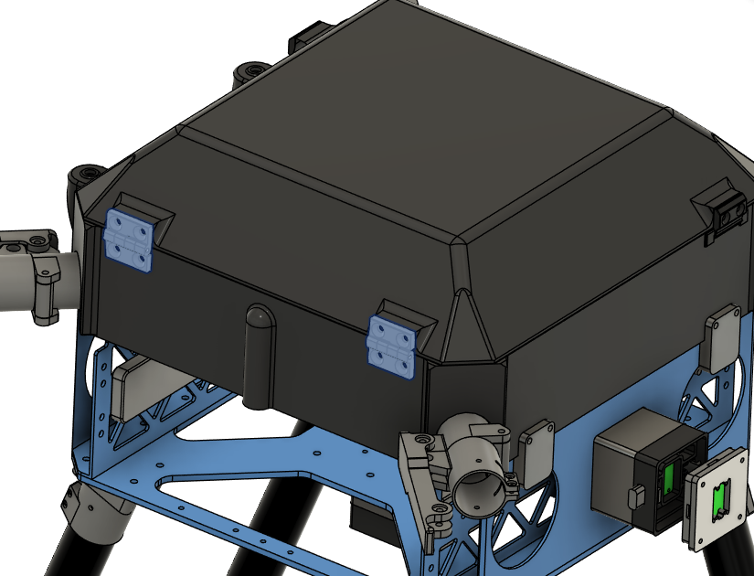
Step 11. Install Cockpit Enclosure
-
Parts needed:
- Step 10 chassis
- Part 27 (Main Enclosure)
- Part 28 (Enclosure Top Cap)
- Part 14 (Enclosure Hinge)
- Part 29 (Enclosure Cap Clips)
- Part 19 (Enclosure Anchors)
- Screw 1 x8
- Screw 7 x8
- Screw 8 x4
- Washer 1 x8
- Insert 1 x20
-
Place Insert 1 to the holes shown in the picture from outside on the main enclosure.
- Use a soldering iron to place them inside the plastic.
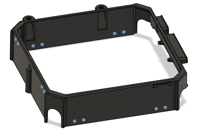
- Place the enclosure anchors and the main enclosure over the chassis.
- The anchors will fit on the circular cutouts on the battery walls.
- Mind the direction of the main enclosure.
- Screw the anchors to the main enclosure with Screw 1.
- Use Washer 1.
- DO NOT use Loctite Threadlocker.

- Place Insert 1 to the holes shown in the picture from outside on the top cap.
- Use a soldering iron to place them inside the plastic.
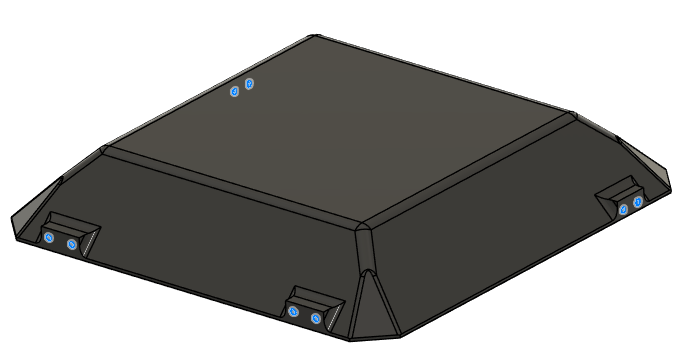
- Place the enclosure clips on the top cap as shown in the picture.
- Screw the anchors to the main enclosure with Screw 8.
- DO NOT use Loctite Threadlocker.
- Screw the anchors to the main enclosure with Screw 8.
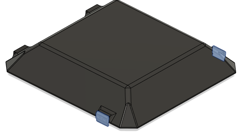
- Place the top cap over the chassis.
- Secure the enclosure hinges on the top cap and the main enclosure.
- Use Screw 7.
- DO NOT use Loctite Threadlocker.
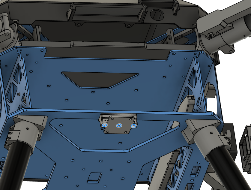
Step 12. Install Altitude Sensor Mount
-
Parts needed:
- Step 11 chassis
- Part 18 (Altitude Sensor Mount)
- Screw 4 x4
- Washer 1 x4
- Nut 1 x4
-
Place Insert 1 to the holes shown in the picture.
- Use a soldering iron to place them inside the plastic.
- Secure the altitude sensor mount on the lower plate.
- Screw head stays inside the mount.
- Use Screw 3.
- Use Washer 1 on the nut side.
- Use Nut 1.
- DO NOT use Loctite Threadlocker.
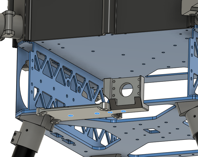
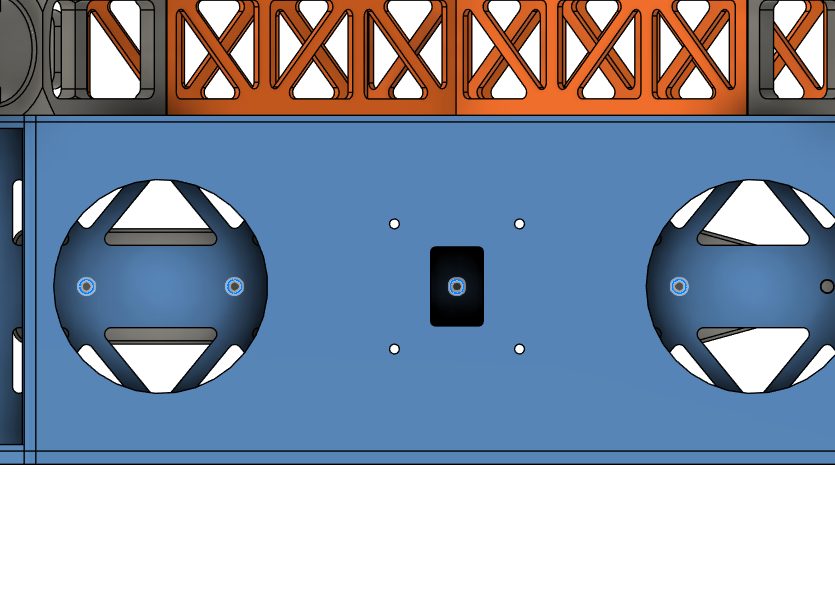
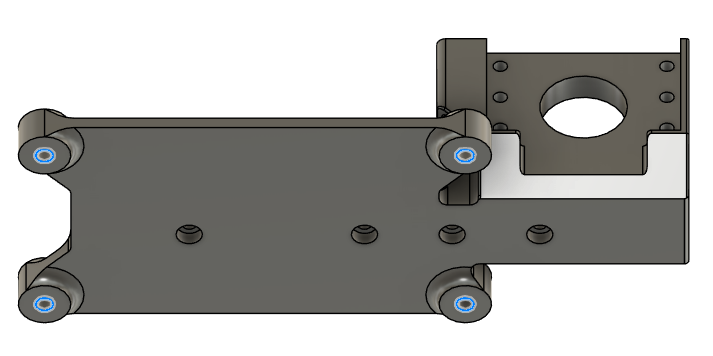
Step 13. Install Camera Mount
-
Parts needed:
- Step 12 chassis
- Part 20 (Camera Mount)
- Screw 10 x3
- Washer 1 x3
- Nut 1 x3
-
Secure the altitude sensor mount on the lower plate.
- Screw head stays under the mount.
- Use Screw 10.
- Use Washer 1 on the nut side.
- Use Nut 1.
- DO NOT use Loctite Threadlocker.
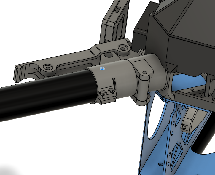
Step 14. Install Motor Arm Tubes
-
Parts needed:
- Step 13 chassis
- Part 10 (Motor Arm Tubes)
- Screw 6 x4
- Washer 1 x8
- Nut 1 x4
-
Insert the motor arm tubes inside the motor arm connectors.
- Make sure the tubes are inserted all the way.
- Tighten the clamps with the screws provided in the motor arm connector package.
- Use Loctite Threadlocker to secure the screws.
- Drill the tubes with 3 mm drill bit on the marked holes.
- Use Screw 6.
- Use Washer 1 on each side.
- Use Nut 1.
- The structural assembly is completed.
- Keep GNSS mount, GNSS mount clamp and BC PCB cover parts for the general assembly.